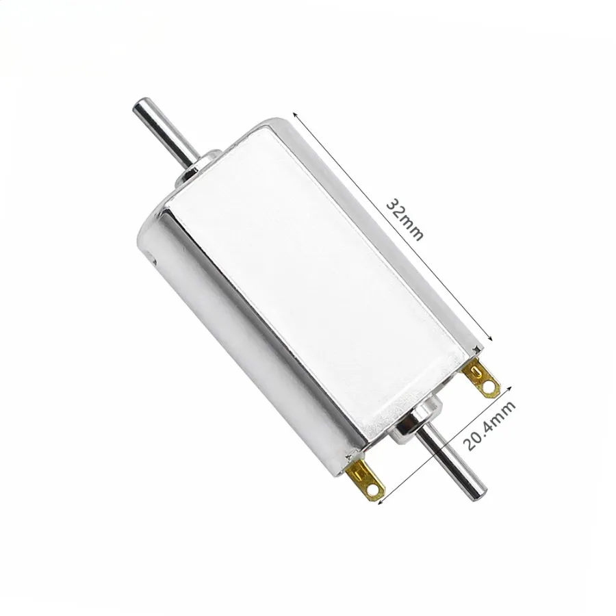
130 Motor
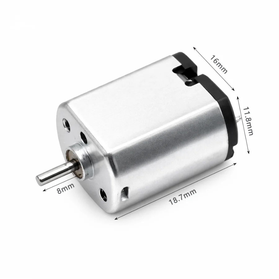
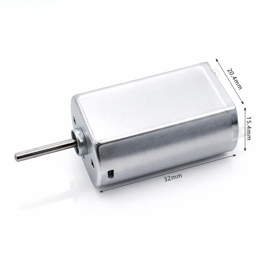
— Flat-can brushed DC motor, approx. 20.1 × 15.4 × 25 mm
— 1.5V to 12V voltage options across available models
— No-load speed from approx. 3,000 to 22,000 RPM, model-dependent
— Custom winding, leads, terminals and spur gearbox configurations
Kechen Motor – 130 Motor Manufacturer in China
Kechen Motor supplies 130 motor models for small electrical and mechanical drive assemblies. This permanent-magnet brushed motor platform uses a flat metal housing measuring approximately 20.1 mm × 15.4 mm, with a typical body length of 25 mm. Available rated-voltage options include 1.5V, 3V, 4.5V, 6V and 12V, giving OEM designers several choices for different power supplies and operating requirements.
Depending on the winding and model, the series covers no-load speeds from approximately 3,000 RPM to selected high-speed versions reaching 22,000 RPM. A 130 electric motor should therefore be selected from its actual voltage, speed, current, shaft dimensions and load requirements rather than from the 130 designation alone. Engineers comparing a broader 130 DC motor range can also review the dedicated technical guide for additional selection information.
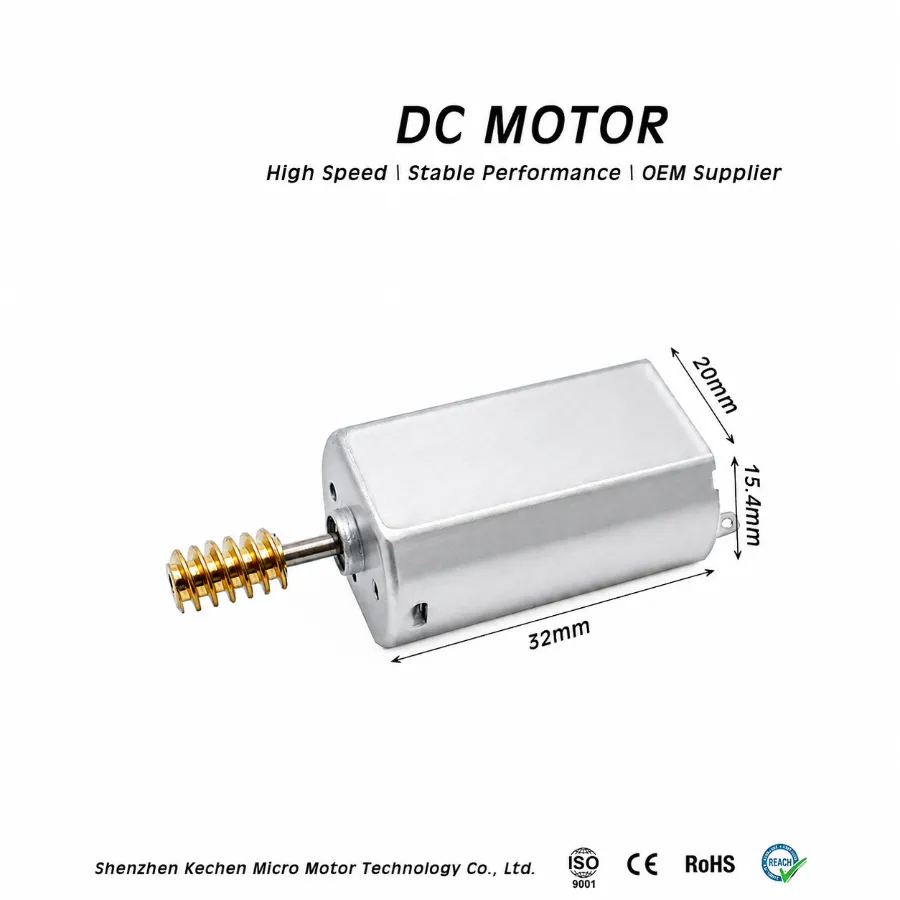
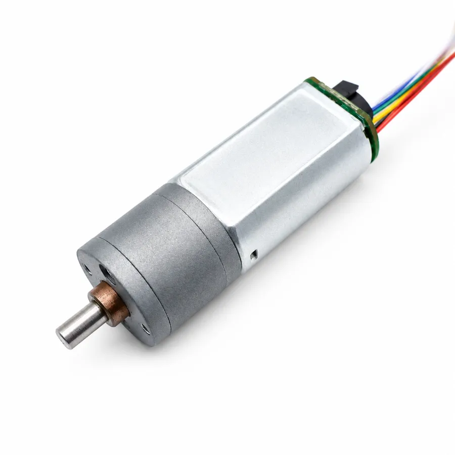
The motor can be used as a direct-drive unit or matched with a spur gearbox when lower output speed is required. This gives the 130 type motor a practical role in locks, home mechanisms, counters, ticket equipment, small sorting devices and laboratory equipment.
View Kechen 130 DC Motor Products Now
130 Motor Shaft, Winding and Connection Options
A standard configuration does not always match the mechanical interface or electrical target of an OEM assembly. A custom 130 motor can be specified around the required winding, shaft and connection details while retaining the same general motor platform.
- 1.5V, 3V, 4.5V, 6V and 12V winding options
- Speed selection according to winding and rated voltage
- Custom output shaft length for different coupling positions
- D-cut and knurled shaft configurations
- Carbon or precious-metal brush options
- Pre-soldered leads and custom terminal arrangements
- Optional varistor for EMC suppression
- Spur gearbox matching with custom reduction ratios
For an OEM 130 motor project, 2D or 3D drawings can be reviewed before production. Physical samples can then be checked for shaft fit, dimensions and operating parameters before volume manufacturing.
130 Size Motor Construction and Mechanical Interface
A 130 size motor uses a flat rectangular housing rather than the cylindrical construction found on many other small DC motors. In this series, the body is approximately 20.1 mm wide and 15.4 mm thick, with a typical length of 25 mm. The output shaft is generally 2 mm in diameter, while shaft projection can vary from about 7 to 12 mm depending on the model.
The 130 designation should not be treated as one fixed mechanical or electrical standard. A 130 size DC motor may use a different winding, rated voltage, no-load current, speed or shaft arrangement while maintaining a similar housing format. For exact dimensions, shaft positioning and mounting considerations, refer to the dedicated 130 motor size guide.
As a 130 brushed motor platform, the series can also use carbon or precious-metal brush configurations. Selected models can be supplied with D-cut or knurled shafts, pre-soldered leads and gearbox matching for mechanisms that require a different output interface.
130 Motor Electrical and Mechanical Range
| Parameter | 130 Motor Series Range |
|---|---|
| Motor Type | Permanent-magnet brushed DC motor |
| Motor Body Size | Approx. 20.1 mm × 15.4 mm, 25 mm body length |
| Rated Voltage | 1.5V / 3V / 4.5V / 6V / 12V |
| Operating Voltage Range | Typically 1.5V–12V |
| No-load Speed | Approx. 3,000–22,000 RPM, model-dependent |
| No-load Current | Approx. 70–250 mA, model-dependent |
| Weight | Approx. 17–20 g |
| Output Shaft Diameter | 2 mm |
| Output Shaft Length | Approx. 7–12 mm, model-specific |
| Gearbox Options | Spur gearbox configurations with custom reduction ratios upon request |
| Available Options | Carbon or precious-metal brushes, varistor, D-cut or knurled shaft, pre-soldered leads |
Product Documents & Downloads
| Document Description | File Details |
|---|---|
| KC-130SH-38 12V Brushed DC Motor Drawing & Performance Curve | PDF · English · 209 KB |
| KC-130SH-38L 5V Brushed DC Motor Drawing & Performance Curve | PDF · English · 229 KB |
| KC-130SH-42 2.4V Brushed DC Motor Drawing & Performance Curve | PDF · English · 209 KB |
| KC-130SH-45 6V Dual Output Shaft Brushed DC Motor Drawing & Performance Curve | PDF · English · 241 KB |
Kechen 130 DC Motor Products
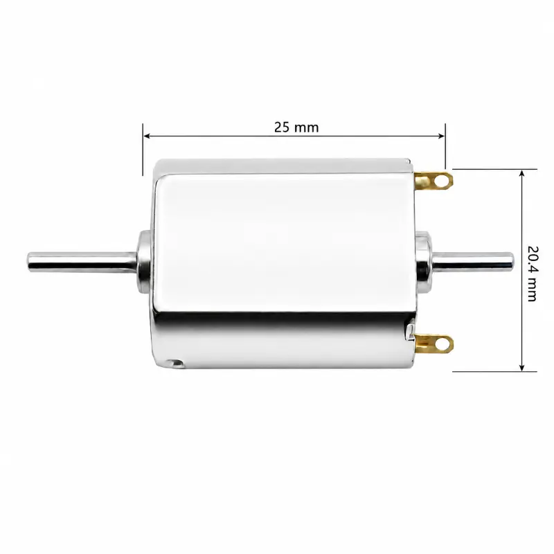
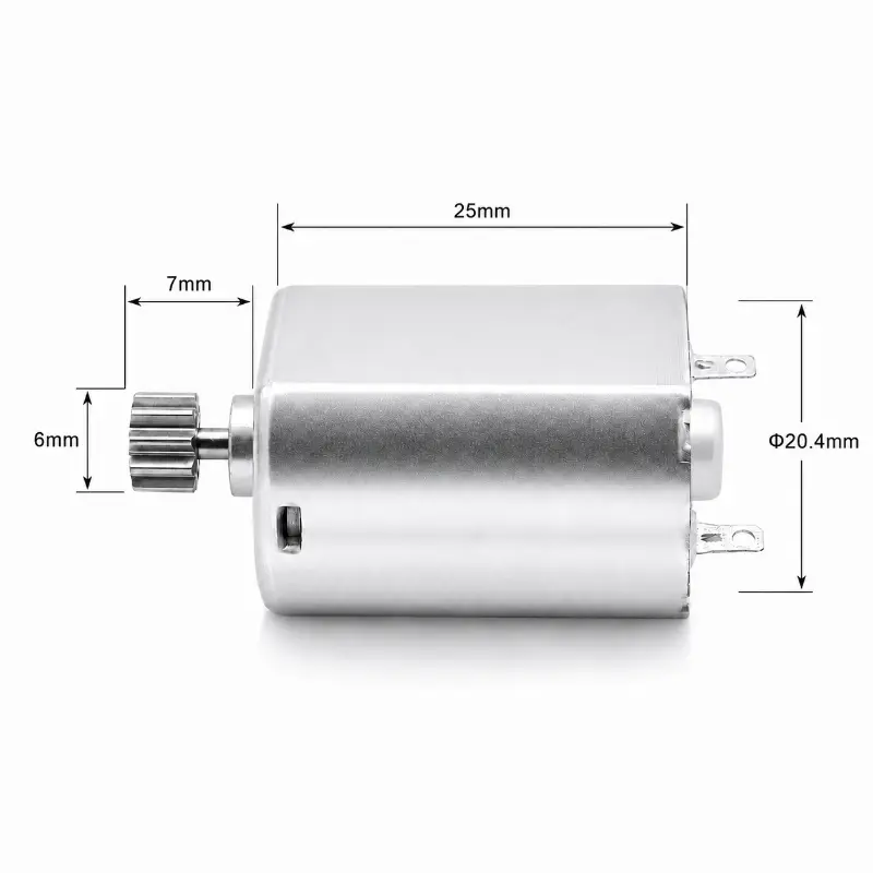
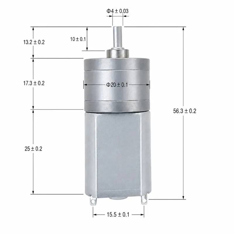
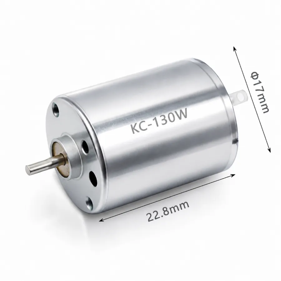
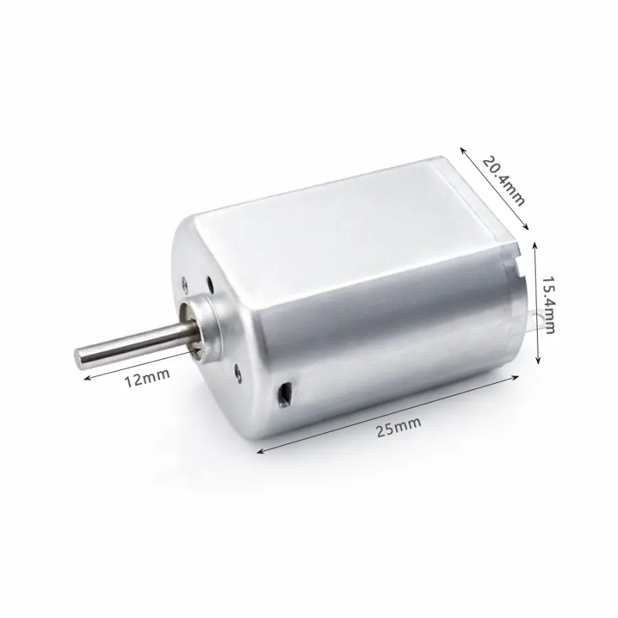
Kechen 130 Motor 3D Design
Applications for the 130 Motor Series
The flat housing, low-voltage winding choices and broad speed range allow the 130 motor series to be used in several types of small drive mechanisms. The required configuration depends on the available space, target speed, load and whether the motor operates directly or through a gearbox.
-
Smart Home & Access Mechanisms
130 motor models can drive automated door locks, smart blinds and related mechanisms where a flat motor body helps reduce installation space.
-
Commercial Handling Equipment
Currency counters, ticket dispensers and small sorting mechanisms can use different winding and shaft configurations according to their required operating speed.
-
Monitoring & Laboratory Mechanisms
Selected versions can be used in portable monitoring equipment, meteorological devices, laboratory mixers and automated testing mechanisms.
Selecting a 130 Motor for an OEM Project
Motor selection should start from the mechanism rather than from the 130 designation alone. For direct-drive applications, target RPM and load are usually the first electrical checks. Projects using a gearbox also need the required output speed and mechanical interface to be confirmed.
- Confirm the available supply voltage and target operating speed
- Provide load or torque information when available
- Check the 2 mm shaft interface, required shaft length and coupling method
- Confirm available mounting space and surrounding mechanical clearance
- Specify any D-cut, knurled shaft, lead-wire or terminal requirements
- Review spur gearbox requirements when speed reduction is needed
- Use drawing review and physical samples to confirm the final configuration
Typical production lead time is 15–25 days depending on specification complexity and material scheduling. Standard shipment preparation uses anti-static trays, export cartons and internal moisture protection.
| View Kechen 130 DC Motor Products Now | Customize Your 130 Motor |