

Micro Motor Blogs
130 Motor Size Guide: Dimensions, Shaft Size, and Mounting Specifications
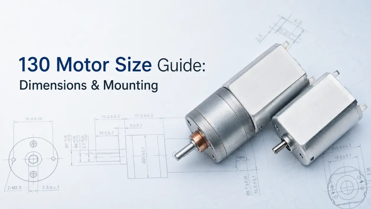
The 130 motor size is commonly used in the small DC motor market, but “130” should not be interpreted as a universal mechanical standard. Motors sold within this size category can differ in housing geometry, shaft projection, mounting details, and end-cap construction. For engineers, technicians, and procurement teams, the practical task is not simply to identify another 130 size motor, but to confirm whether its physical interface matches the equipment. Body dimensions, shaft diameter, mounting-hole location, terminal clearance, and overall installed length should all be checked against the actual motor drawing before a replacement or new design is approved.
130 Motor Size and Common Flat-Can Dimensions
Many 130 motor products use a flat rectangular metal housing with dimensions close to 25 mm in body length and roughly 20 × 15 mm across the housing. These values are useful as general market references for a typical 130 size dc motor, but they are not fixed dimensional requirements. Exact dimensions remain dependent on the individual motor design, manufacturing tooling, end-cap structure, shaft configuration, and intended mechanical interface.
This distinction is important because the 130 designation is a commercial size or series reference rather than an IEC- or NEMA-style frame specification. A 130 type motor can therefore differ from another 130 motor in body length, housing profile, front bearing structure, or mounting arrangement even when both products are described using the same general size term.
For common flat-can designs, a useful engineering reference range is approximately 25.0–25.1 mm in body length, 20.1–20.4 mm in body width, and 15.1–15.4 mm in body height. A shaft near Ø2.0 mm is also common in this category. These figures should be used only for preliminary comparison. They do not replace the dimensional drawing supplied for the actual 130 electric motor being evaluated.
Engineers should separate motor-body dimensions from total installed dimensions. The nominal body length may exclude the exposed shaft, pinion, rear shaft, terminal projection, connector, solder joint, or lead-wire bend. A housing that fits within the available cavity can still interfere with surrounding components if these additional features are not included in the mechanical envelope.
The following values describe common flat-can references and should not be treated as a universal dimensional standard.
| Parameter | Common Flat-Can Reference | Engineering Check |
|---|---|---|
| Motor body length | Approximately 25.0–25.1 mm | Confirm the reference surfaces and whether the end cap is included |
| Body width | Approximately 20.1–20.4 mm | Check bracket and enclosure clearance |
| Body height | Approximately 15.1–15.4 mm | Check the available installation envelope |
| Shaft diameter | Ø2.0 mm is common on many flat-can designs | Confirm nominal diameter, tolerance, and mating bore |
| Overall installed length | Model-dependent | Include shaft, terminal, pinion, coupling, or rear extension as required |
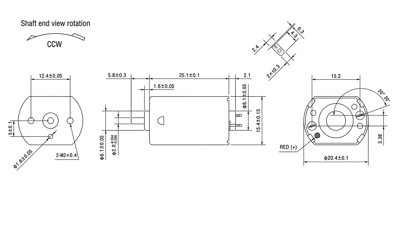
A difference of only a few tenths of a millimeter can become relevant when the motor is retained by molded ribs, inserted into a fixed metal bracket, or positioned inside a gearbox housing. A product with a similar 130 motor size may enter the available space but fail to seat correctly because the bearing projection, end-cap geometry, or terminal structure differs. The approved dimension drawing should therefore remain the controlling mechanical reference.
130 Motor Size: Shaft Diameter, Length, and Mechanical Fit
The shaft is one of the most important dimensions when comparing a 130 size dc motor with an existing assembly. A shaft near Ø2.0 mm is common on many flat-can designs, but nominal diameter alone is not sufficient for engineering approval. Exposed shaft length, manufacturing tolerance, surface condition, shaft profile, and the axial reference point all influence whether a gear, coupling, or pulley can be installed correctly.
Round shafts are widely used on the 130 brushed motor category. D-shaped shafts and other modified profiles may be specified for customized applications, but they should not be assumed to be standard features of every 130 motor. A drawing should clearly identify whether the shaft is round, D-shaped, double-ended, threaded, or supplied with an installed pinion.
Shaft tolerance becomes particularly important when a pinion is press-fitted. If the shaft-to-bore interference is too small, the pinion may move or slip when torque is transmitted. If the interference is excessive, assembly force rises and may damage the pinion, overload the front bushing, or deform the supporting structure. In a production gearbox, both the motor shaft tolerance and the mating pinion-bore tolerance should therefore be specified rather than relying on nominal dimensions alone.
Shaft projection must also be measured from the correct reference surface. Depending on the drawing, this reference may be the front housing face, bearing projection, or another stated datum. Two motors with a similar 130 motor size and the same nominal shaft diameter can still position a pinion at different axial locations. In a geared mechanism, that difference can reduce tooth engagement or create contact with an adjacent housing feature.
Some 130 motor configurations use a rear shaft for an encoder or another secondary mechanical interface. A dual-shaft configuration requires additional rear clearance and should be evaluated separately from a single-shaft version. The extra shaft length can also affect enclosure design, wiring space, and the position of any rear-mounted sensing component.
Mounting Dimensions, Hole Spacing, and Front-Face Geometry
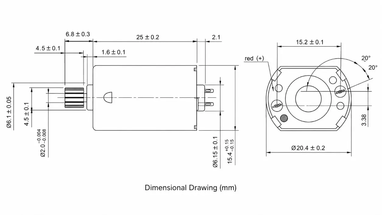
A matching 130 motor size does not guarantee an identical mounting interface. Some 130 motor designs use threaded front mounting holes, while others rely on brackets, clips, press-fit housings, or application-specific mounting structures. Hole diameter, thread specification, center-to-center spacing, front-boss geometry, and shaft centerline should therefore be treated as model-specific dimensions.
Mounting-hole center distance is especially important when a motor is attached to a machined plate, stamped-metal bracket, or molded carrier. Even a small dimensional difference can prevent the screws from aligning correctly. Forcing the motor into position can shift the shaft centerline and affect the driven mechanism.
In a gearbox, shaft position directly affects the center distance between the motor pinion and the first driven gear. If the motor sits too high, too low, or too far to one side, tooth engagement can move outside the intended condition. This can increase noise, change contact loading, or create uneven wear. The mounting interface should therefore be evaluated together with the gearbox geometry rather than as an isolated motor specification.
The front bearing or bushing projection also requires attention. When the mating bracket is designed around this feature, the boss can help locate the motor relative to the driven component. Its diameter and projection must match the receiving structure. A different front geometry may prevent the motor from seating fully or place the shaft at an unintended axial position.
For engineering approval, the mounting review should include hole diameter or thread specification, center spacing, locating features, shaft centerline, front-face clearance, and screw engagement where screws are used. These values should be taken from the actual drawing rather than inferred from the words 130 size motor.
How to Read a 130 Motor Dimension Drawing
A motor drawing provides the information required to determine whether the 130 motor size can be integrated into an existing mechanism. The most practical review begins with the external envelope and then moves toward the driven interface.
First, identify the motor body length, width, and height. These dimensions establish the basic installation space. Second, check the total axial length, including any front or rear shaft extension shown on the drawing. Third, verify shaft diameter and exposed shaft length. Fourth, review mounting-hole locations, front locating geometry, and shaft centerline. Finally, inspect terminal orientation and the rear clearance required for solder connections or lead wires.
The symbol Ø indicates diameter. A drawing value such as Ø2 describes a nominal 2 mm dimension, but it should not automatically be interpreted as exactly 2.000 mm. The applicable tolerance determines the permitted manufacturing range. This distinction matters when a shaft enters a precision coupling or when a pinion is installed by interference fit.
For a micro 130 dc motor installed in a space-limited assembly, the terminal arrangement can be as important as the metal housing dimensions. The motor body may clear the enclosure while the solder terminals or wires contact a rear wall. Wire routing and bend space should therefore be included when checking the installed envelope.
Before a bracket, mold, gearbox plate, or machining fixture is released for production, confirm that the drawing uses the expected unit system and review all applicable tolerance notes, reference surfaces, and revision information. This avoids designing production hardware around an outdated or incorrectly interpreted 130 motor size.
Do All 130 Size DC Motors Have the Same Dimensions?
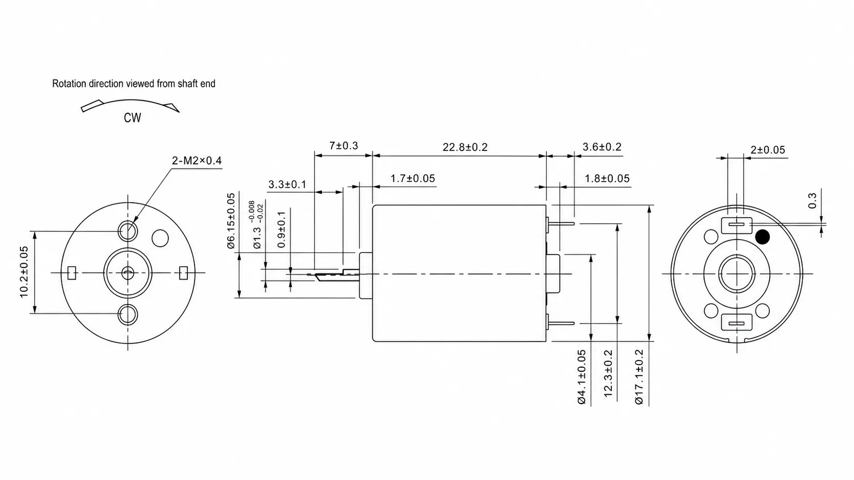
No. The 130 motor size is not a universal dimensional standard. It is used across multiple small DC motor designs, and the exact mechanical geometry remains dependent on the individual series, supplier, and application configuration.
Differences may appear in body dimensions, front-bushing construction, shaft length, end-cap profile, mounting features, terminal position, and shaft form. Some products remain close to the familiar flat-can envelope of approximately 20 × 15 × 25 mm, while others may use a different housing geometry despite carrying a 130 designation.
This distinction is important when sourcing a type 130 dc motor as a replacement. The size description can narrow the initial product search, but dimensional interchangeability should be established from drawings and tolerances. A 130 size brushed motor that is electrically suitable can still be mechanically incompatible if the shaft projection, mounting interface, front boss, or terminal arrangement differs from the original component.
Procurement documentation should therefore include a drawing number or a controlled list of critical dimensions rather than relying only on 130 motor size in the part description. This provides engineering and incoming-inspection teams with measurable acceptance criteria.
Does Voltage Determine the 130 Motor Size?
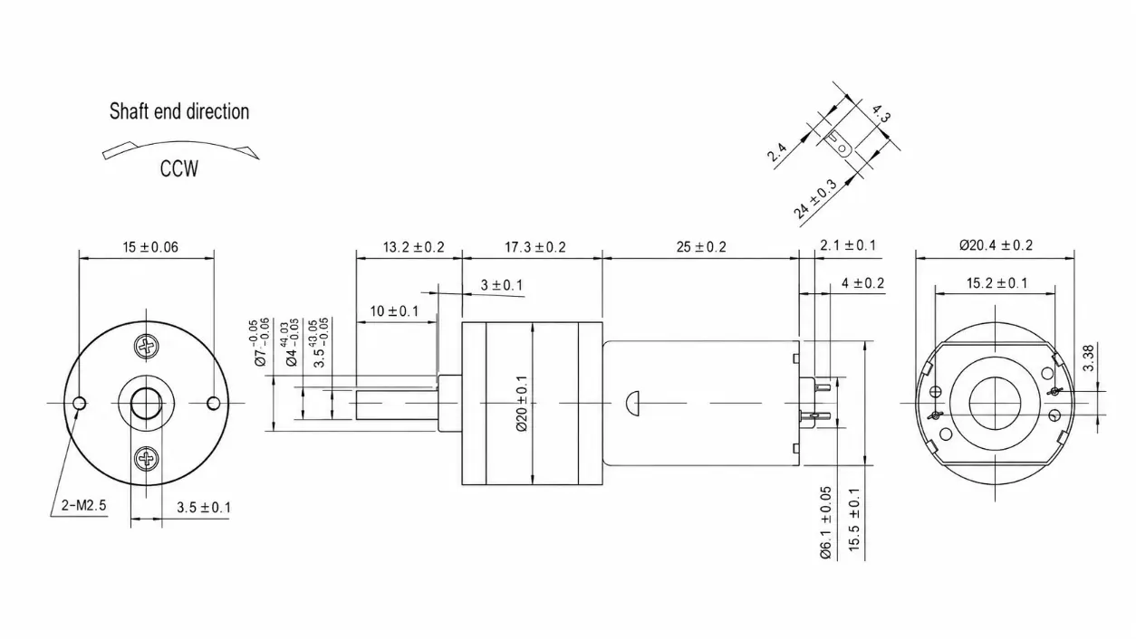
Voltage and 130 motor size describe different parts of the motor specification. Mechanical dimensions determine whether the motor can be installed, while winding design and rated voltage influence electrical behavior. Similar housings can be used with different winding configurations, so motors that look nearly identical may have different rated voltages, current characteristics, speed ranges, and winding resistance.
A 130 dc motor 12v should therefore not be selected as a mechanical replacement simply because the existing motor also operates from 12 V. Likewise, a lower-voltage 130 dc motor may use similar external dimensions without being electrically interchangeable.
For an OEM replacement, mechanical and electrical checks should be separated. Mechanical verification covers the housing envelope, shaft geometry, mounting interface, terminal position, and available installation clearance. Electrical verification covers rated voltage, current, required loaded speed, load point, and duty conditions.
The same principle applies when sourcing a high torque 130 motor. A higher torque requirement may affect winding selection, operating point, or the need for a gearbox, but the phrase does not define a separate standardized housing size. Torque should be evaluated from actual performance data and the required load condition rather than inferred from the mechanical designation.
130 Motor Dimensions in Small Mechanisms
The 130 motor size is frequently considered for small electromechanical mechanisms because common flat-can versions require a limited installation envelope and can be combined with gears, couplings, and other driven components. The same general product category can appear in model equipment, educational mechanisms, small office equipment, printing mechanisms, vending devices, and other light-duty assemblies.
The search phrase dc toy hobby motor 130 size is also associated with this general motor category, but an OEM specification normally requires more information than a consumer-style size description. A basic model application may use a simple retaining bracket, whereas a production gearbox may require controlled shaft position, repeatable mounting-hole location, defined pinion fit, and dimensional inspection criteria.
Application names should therefore not replace mechanical data. Even when two assemblies both specify a 130 motor, their required shaft length, mounting method, available clearance, driven load, and wiring arrangement may differ. The receiving structure determines whether a particular 130 size dc motor can be integrated without changes to the surrounding mechanism.
Selecting the Correct 130 Motor Size for an OEM Project
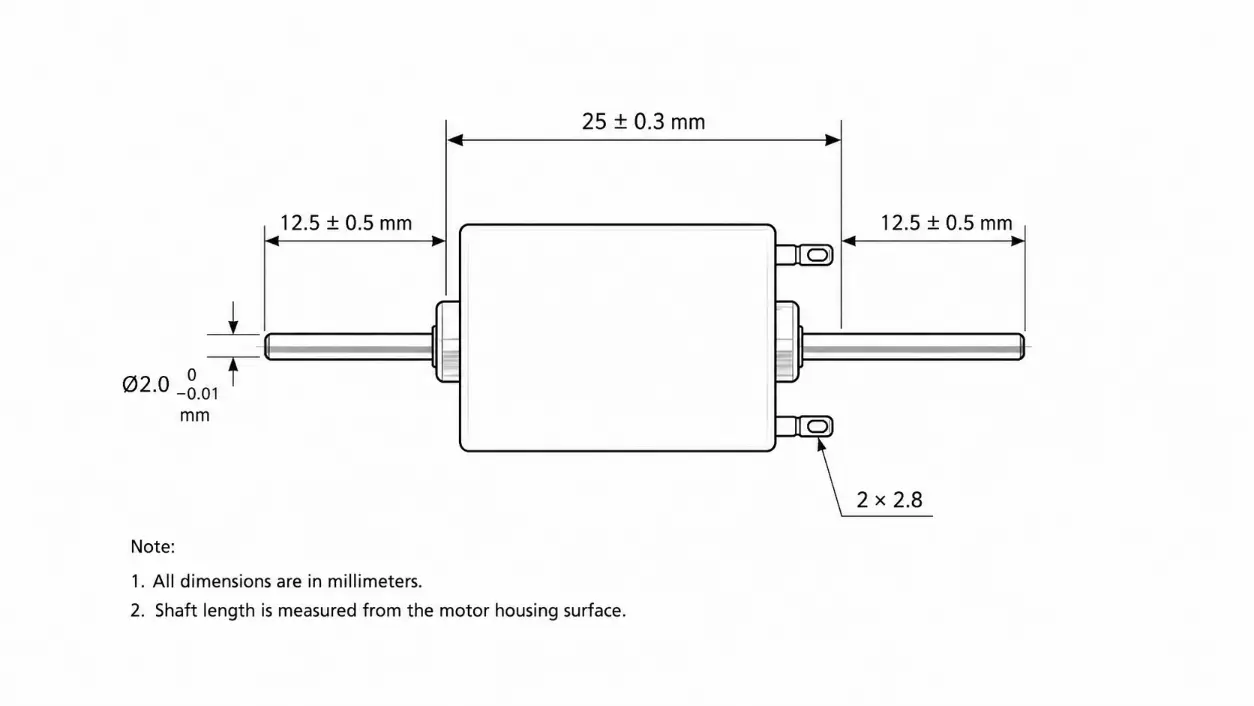
OEM selection should begin with the available mechanical envelope rather than with a general product name. Record the maximum allowable body length, width, height, front clearance, rear clearance, shaft centerline, and mounting interface. These limits establish whether a candidate 130 motor size can be positioned correctly inside the equipment.
The shaft specification should then define diameter, tolerance, usable projection, profile, and any required gear or coupling interface. If a press-fit pinion is used, the pinion bore and assembly method should also be defined. If a D-shaped shaft is required, specify the D-flat dimensions and angular position rather than requesting a generic D-shaft.
Mounting requirements should include hole diameter or thread, center spacing, locating features, front-face geometry, and any dimensions that directly influence shaft alignment. Electrical requirements should be documented separately, including rated voltage, required loaded speed, operating current limits where relevant, duty condition, and driven load.
Where a standard 130 brushed motor does not match the application, selected mechanical details may be customized according to manufacturing capability. These can include shaft length, shaft profile, dual-shaft construction, pinion installation, lead-wire arrangement, or other application-specific interfaces. Each requirement should be communicated through a dimension drawing or controlled specification rather than through descriptive wording alone.
For sample evaluation, engineers and procurement teams can provide the existing motor drawing, installation drawing, physical sample information, target voltage, loaded speed, load condition, duty cycle, and expected production quantity. These inputs allow dimensional compatibility and operating requirements to be reviewed together.
For bulk production, dimensions that directly affect fit or function should be identified as critical characteristics. Incoming inspection can then focus on measurements that influence assembly performance, such as shaft diameter, shaft projection, mounting position, and body dimensions. This approach is more controlled than approving a part only because it is described as a 130 electric motor.
Key Mechanical Checks Before Approval
A practical 130 motor size review can be reduced to several drawing-controlled checks. Confirm the body envelope first, then verify shaft diameter and projection, mounting location, front locating features, and terminal clearance. Electrical requirements should be checked separately against the required voltage, loaded speed, current, and load condition.
| Check | Why It Matters | Possible Result if Incorrect |
|---|---|---|
| Body envelope | Defines available installation space | Motor cannot seat fully in the housing or bracket |
| Shaft diameter and tolerance | Controls fit with a gear or coupling | Loose fit, excessive press force, or poor concentricity |
| Shaft projection | Controls axial position of the driven component | Incorrect gear engagement or mechanical interference |
| Mounting position | Controls motor location and shaft alignment | Screw misalignment or incorrect gear center distance |
| Front locating geometry | May control motor position in the mating structure | Motor does not seat or locate as specified |
| Terminal clearance | Provides space for electrical connection | Interference with the enclosure or wiring path |
The central engineering value of the 130 motor size is as an initial classification; final mechanical compatibility must be established from the actual dimensions, tolerances, and installation interface.
130 Motor Size FAQ
Is 20 × 15 × 25 mm the standard size for every 130 motor?
No. Dimensions close to 20 × 15 × 25 mm are common among flat-can 130 motor designs, and typical reference ranges include approximately 20.1–20.4 mm in width, 15.1–15.4 mm in height, and 25.0–25.1 mm in body length. These are useful reference dimensions rather than a universal 130 motor size standard. Exact values should always be confirmed from the drawing for the motor being sourced.
Does a 2 mm shaft mean two 130 motors are interchangeable?
No. Ø2.0 mm is common on many flat-can 130 motor designs, but shaft diameter is only one part of the mechanical interface. Shaft projection, dimensional tolerance, front-face geometry, mounting position, total installed length, and terminal arrangement must also be checked. When a pinion is press-fitted, shaft and pinion-bore tolerances should be reviewed together because the nominal 2 mm value alone does not define the required interference.
Can two motors with the same 130 designation have different mounting dimensions?
Yes. The 130 designation does not impose one universal mounting pattern. Threaded holes, brackets, clips, front locating features, and hole spacing can vary by design. A replacement should therefore be approved from its current dimensional drawing, especially when the motor position controls alignment between a pinion and the first gear in a gearbox.