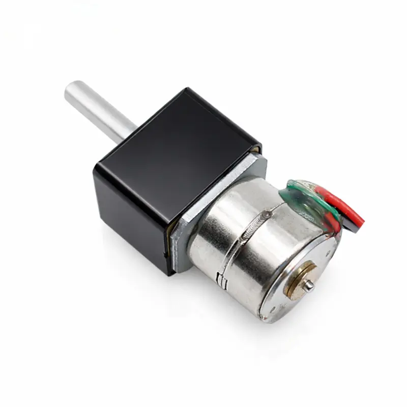
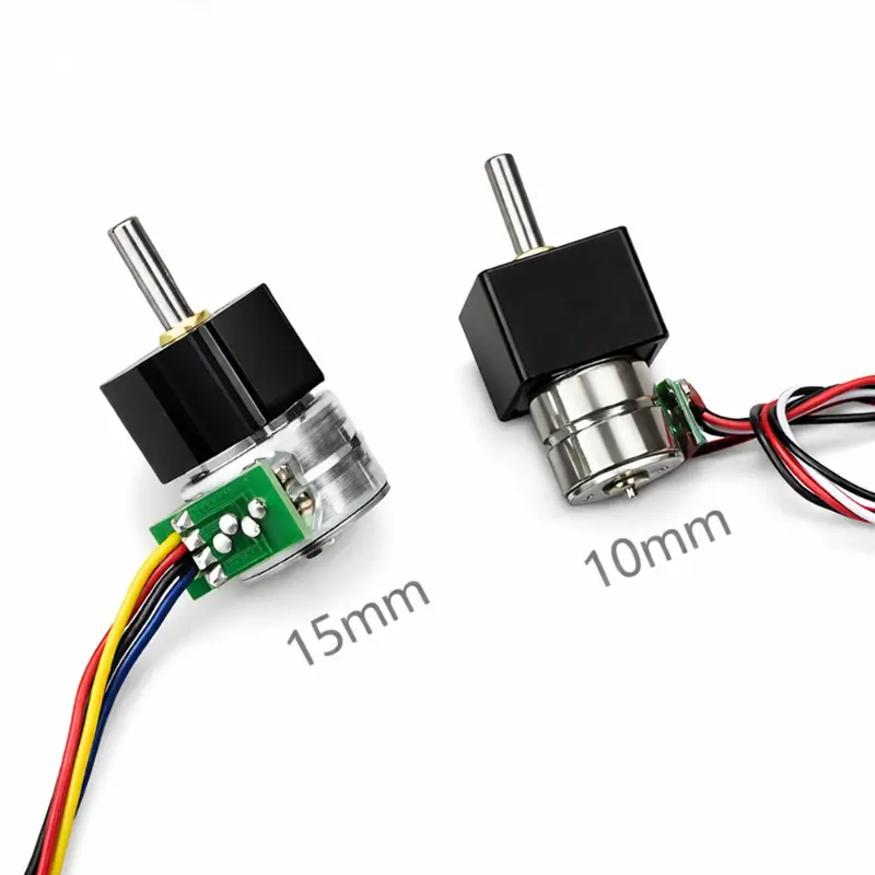
10mm Dustproof Geared Stepper Motor 5V DC 3mm D-Shaft KC-GM12-10BY
Applications: Precision optical lens actuators, medical syringe pumps, electronic smart lock mechanisms, handheld barcode scanner shutters, miniature robotic joints, automated fluid dosing systems, camera iris controls, motorized valve positioners.
Inquiry NowKC-GM12-10BY Geared Stepper Motor Specifications
General and Electrical Specification Parameters
| Parameter | Specification |
|---|---|
| Model Designation | KC-GM12-10BY |
| Motor Architecture | 2-Phase 4-wire PM stepper motor |
| Application Classification | Geared stepper motor |
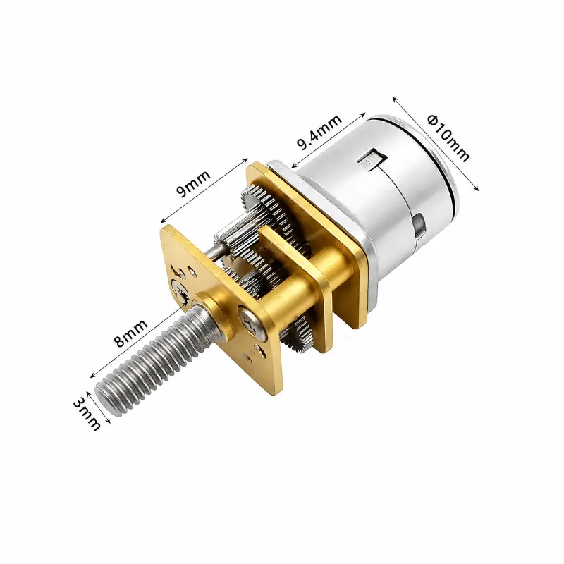
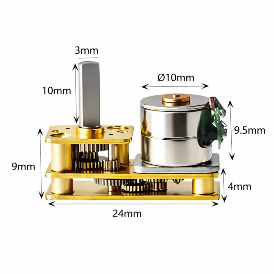
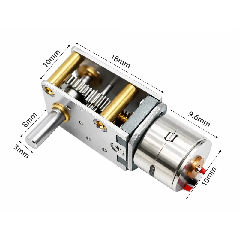
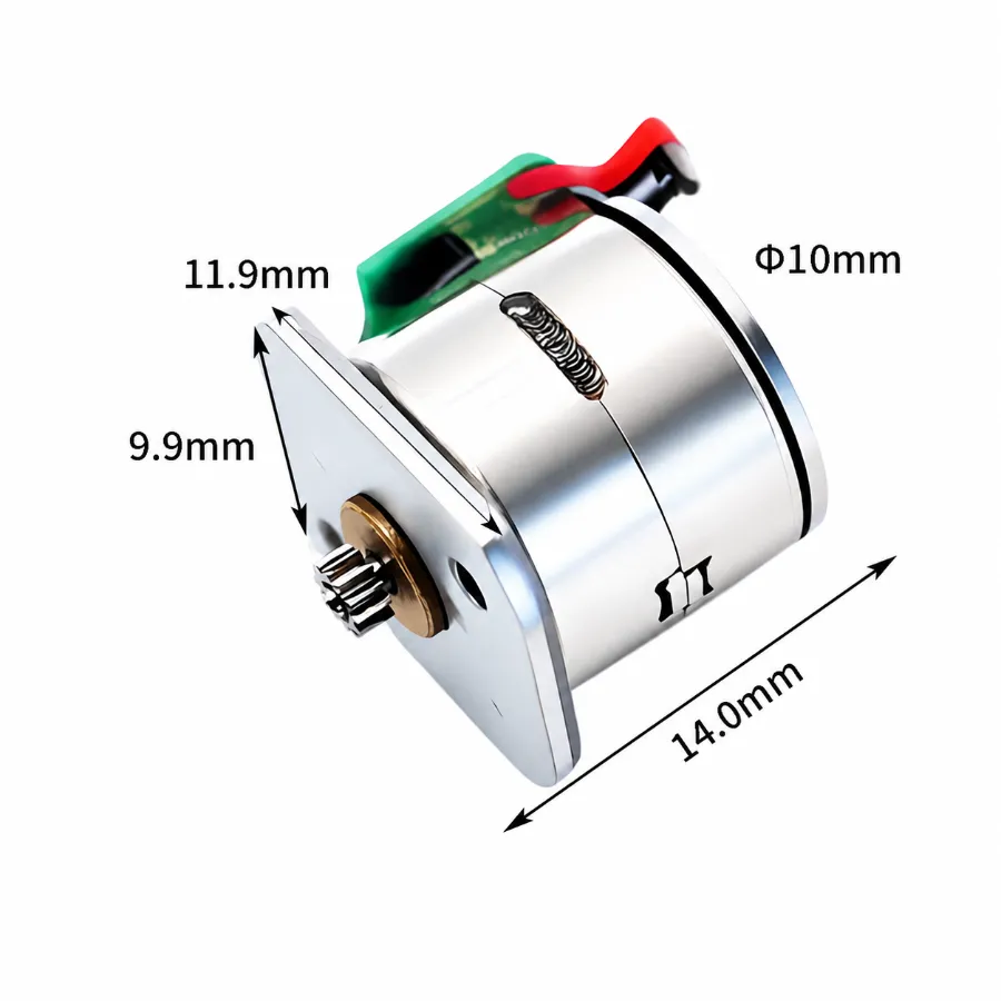
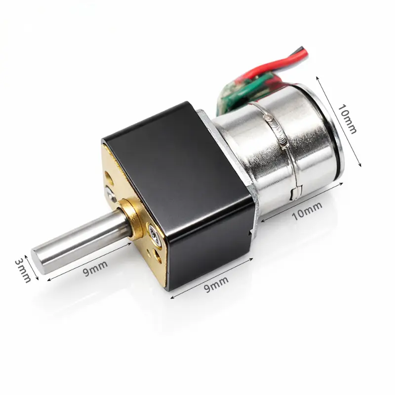
| Motor Diameter | Φ10 mm |
| Gearbox Cross Section | 12 mm × 10 mm (Standard N20 specifications) |
| Total Motor Thickness | 18.6 mm |
| Gearbox Length | 9 mm |
| Nominal Operating Voltage | 5.0 V DC / 12.0 V DC |
| Phase Resistance Options | 10 Ω / 20 Ω / 30 Ω / 40 Ω / 50 Ω (Optional) |
| Phase Current Rating | 490 mA (10 Ω) / 320 mA (20 Ω) / 190 mA (40 Ω) |
| Native Step Angle | 18°/step (Motor side) |
| Reduced Step Angle Range | 0.05°/step to 1.80°/step (Depending on ratio) |
| Excitation Method | 2-2 Phase excitation |
| Detent Torque | 6.0 gf·cm |
| Holding Torque | 18.0–20.0 gf·cm |
| Rated Output Torque | 0.5 kg·cm – 2.5 kg·cm |
| Shaft Specification | 3.0 mm D-shaft / M4 threaded shaft (Custom length available) |
| Wiring Lead Assignment | Red A+ / White A− / Black B− / Brown B+ |
| Lead Wire Length | 30 ± 10 mm |
| Insulation Resistance | 50 MΩ Min at 300 V DC |
| Acoustic Noise Level | ≤ 50 dB |
| Operating Temperature Range | 10 °C to 50 °C |
| Total Unit Weight | 12 g |
| Compliance Standard | RoHS compliant |
KC-GM12-10BY Dynamic Gearbox Performance Data Table
Measured Performance Characteristics Tested at 800 pps Pulse Rate
| Gear Ratio | Stages | Gearbox Length | Step Angle | Pull-out Torque (10 Ω) | Pull-out Torque (20 Ω) | Pull-out Torque (40 Ω) | Speed |
|---|---|---|---|---|---|---|---|
| 10:1 | 2 | 9 mm | 1.80°/step | 84 gf·cm | 51 gf·cm | 34 gf·cm | 240 rpm |
| 20:1 | 3 | 9 mm | 0.90°/step | 147 gf·cm | 90 gf·cm | 59 gf·cm | 120 rpm |
| 30:1 | 3 | 9 mm | 0.60°/step | 221 gf·cm | 134 gf·cm | 88 gf·cm | 80 rpm |
| 50:1 | 4 | 9 mm | 0.36°/step | 315 gf·cm | 192 gf·cm | 126 gf·cm | 48 rpm |
| 75:1 | 4 | 9 mm | 0.24°/step | 473 gf·cm | 288 gf·cm | 189 gf·cm | 32 rpm |
| 100:1 | 4 | 9 mm | 0.18°/step | 630 gf·cm | 384 gf·cm | 252 gf·cm | 24 rpm |
| 165:1 | 5 | 9 mm | 0.11°/step | 866 gf·cm | 528 gf·cm | 347 gf·cm | 14.5 rpm |
| 210:1 | 5 | 9 mm | 0.09°/step | 1 103 gf·cm | 672 gf·cm | 441 gf·cm | 11.4 rpm |
| 250:1 | 5 | 9 mm | 0.07°/step | 1 313 gf·cm | 800 gf·cm | 525 gf·cm | 9.6 rpm |
| 298:1 | 5 | 9 mm | 0.06°/step | 1 565 gf·cm | 954 gf·cm | 626 gf·cm | 8.1 rpm |
| 380:1 | 5 | 0.05°/step | 9 mm | 1 995 gf·cm | 1 216 gf·cm | 798 gf·cm | 6.3 rpm |
KC-GM12-10BY Mechanical Dimensions and Technical Outline
Mechanical Drawing and Geometric Specs for Integration Engineering (Values in mm)
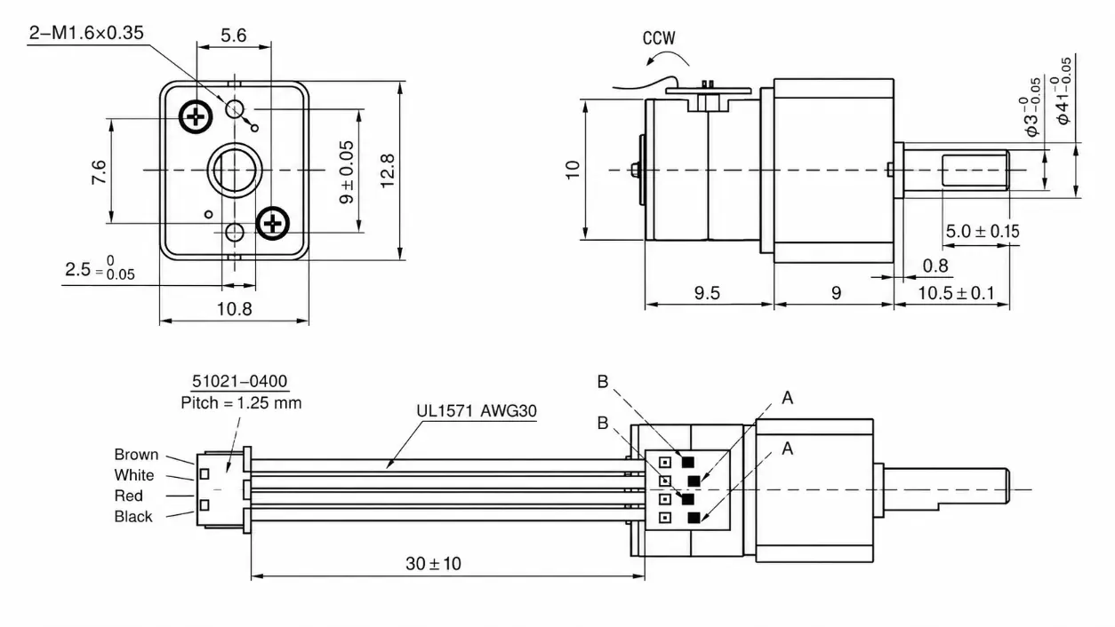
KC-GM12-10BY Geared Stepper Motor Drawing Reference — Standard N20 Gearbox Dimensions (12 mm × 10 mm) with 3.0 mm Outer Shaft Diameter and Black Protective Gear Cover Design (210:1 Assembly Configuration).
KC-GM12-10BY Key Performance Advantages
Technical Benefits for Industrial and OEM System Integration
- High Torque-to-Volume Output: The 12 mm × 10 mm gearbox profile integrates multi-stage spur reduction gears capable of generating up to 2.5 kg·cm rated torque, delivering continuous load capability within tiny stepper motor installations.
- Precision Angular Resolution: Featuring an initial motor step angle of 18°/step scaled down to 0.05°/step across 11 standard reduction ratios, enabling micro-positioning accuracy in open-loop drive modes.
- Adaptable Electrical Winding Options: Multiple phase resistance configurations (10 Ω, 20 Ω, 40 Ω, with optional 30 Ω and 50 Ω) accommodate diverse voltage inputs (5.0 V DC and 12.0 V DC) and current limitations.
- Durable Mechanical Interface: Standard 3.0 mm D-shaft output combined with optional M4 threaded shafting allows compatible coupling with lead screws, precision encoders, and linear positioning stages.
- Stable Bipolar Drive Operation: Standard 2-phase 4-wire configuration operating with 2-2 phase excitation provides low vibrational harmonics, operating acoustic noise below 50 dB, and insulation resistance of 50 MΩ Min at 300 V DC.
- Modular Industrial Customization: Custom options include lead cable lengths (standard 30 ± 10 mm), special gear ratios, shaft modifications, and protective black dust covers for miniature stepper motors operating in harsh environments.
Integration Guidelines and Operational Notes
1. Mechanical Integrity: Metal gearbox components must remain free of surface rust, oxidation, and deep structural scratches. Handling should be performed using clean finger cots to maintain particulate protection.
2. Lead Wire Handling: Avoid applying direct tensile force or sharp axial strain to the lead cable termination area during assembly.
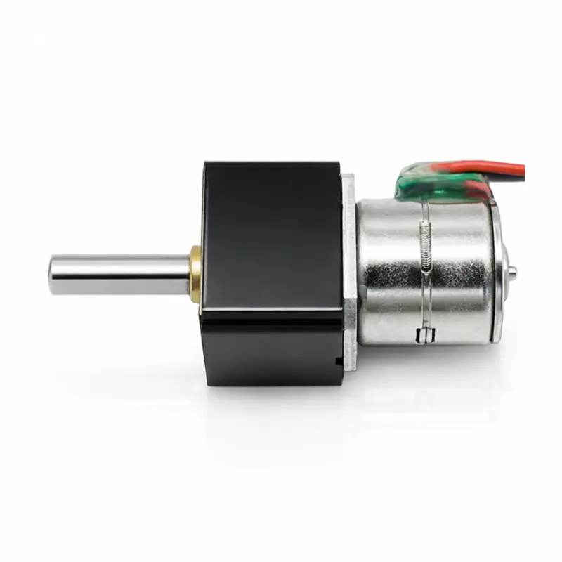
3. Dust Protection Assembly: Model configuration KC-GM12-10BY with a 210:1 reduction ratio incorporates an externally mounted black protective housing for shielding internal gearing mechanisms against external particulate matter.
Technical Search Terms and Key Index Identifiers
geared stepper motor | tiny stepper motor | miniature stepper motors | KC-GM12-10BY | 12 V DC geared stepper motor | 5 V DC tiny stepper motor | N20 form factor geared motor | 10mm outer diameter stepper motor | 2-phase 4-wire bipolar stepper motor | 18 deg step angle motor | 3mm D-shaft miniature stepper motors | high torque tiny stepper motor | precision reduction gear motor | custom gear ratio stepper motor | RoHS compliant geared stepper motor