

Micro Motor Blogs
Smallest Stepper Motor Sizes and the Costly Trade-Offs of Going Smaller
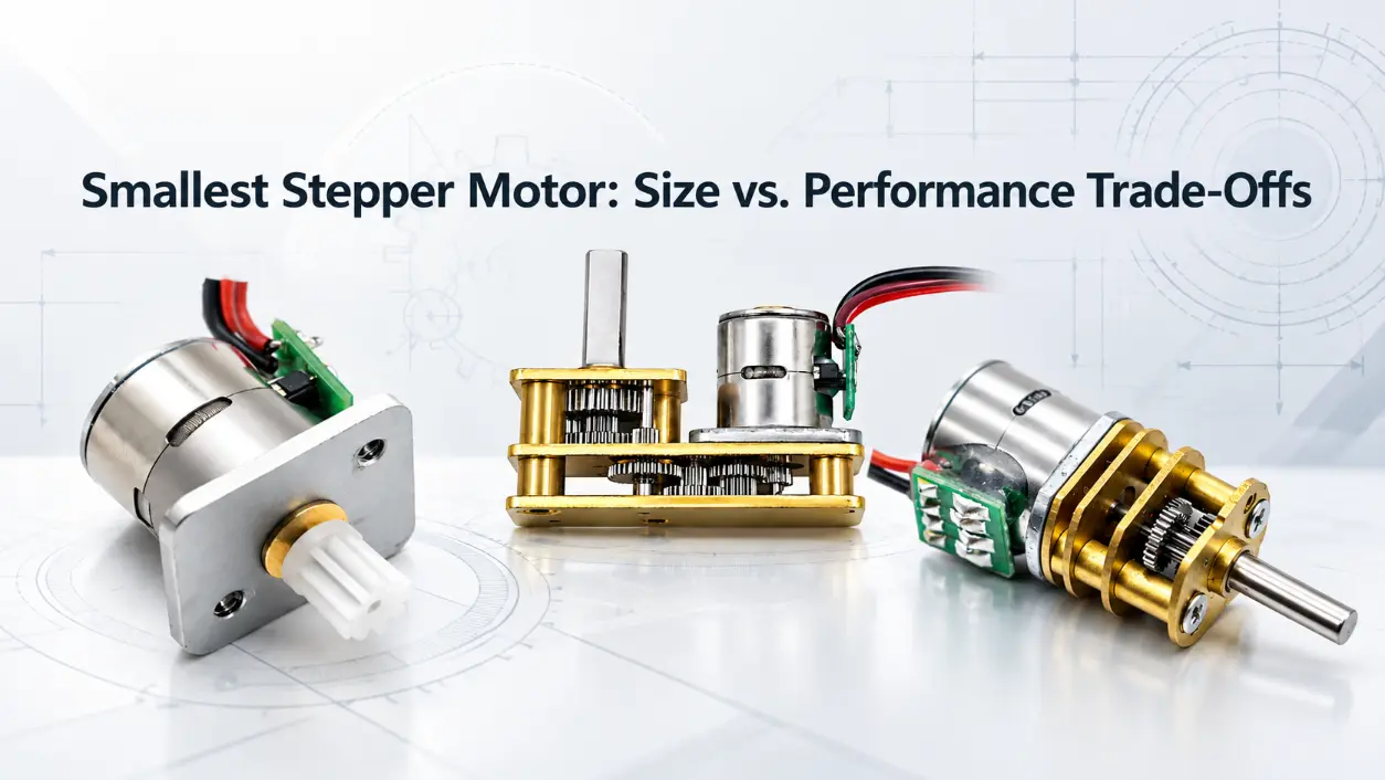
Choosing the smallest stepper motor is not simply a search for the lowest diameter listed in a catalog. In a real mechanism, the motor must still provide enough torque at the required speed, support the shaft load, fit the mounting geometry, and leave usable space for wires and connectors. A motor body can fit inside the available envelope while the complete assembly still fails mechanically. For engineers, the practical question is therefore: how small can the motor become while still meeting torque, positioning, duty-cycle, shaft, and packaging requirements?
Miniature permanent magnet stepper motors are available in several small diameters, including 8, 10, 15, 20, 25, 35, and 42 mm depending on the product family, while small hybrid motors commonly use standardized frame sizes such as NEMA 8, NEMA 11, NEMA 14, and NEMA 17. These groups should not be treated as interchangeable. A miniature stepper selected for a camera mechanism and a hybrid stepper selected for an industrial positioning axis may have similar external dimensions in one direction but very different mounting, electrical, and mechanical characteristics.
How Small Can the Smallest Stepper Motor Actually Be?
There is no universal minimum size for a stepper motor across all applications. The usable minimum depends on torque, operating speed, motor length, shaft dimensions, radial or axial load, mounting arrangement, step angle, winding design, current, and driver conditions. For that reason, the smallest stepper motor for one mechanism may be unsuitable for another mechanism with the same available diameter.
Many miniature permanent magnet stepper motors use round housings and are not constrained to NEMA frame dimensions. This gives equipment designers another packaging option when motor diameter is more restrictive than mounting standardization. An 8 mm or 10 mm small size stepper motor, for example, can be considered where the available installation diameter is extremely limited and the required load remains within the capability of the selected motor.
Physical fit alone is not enough. As motor diameter decreases, the available cross-sectional space for windings, magnetic components, shaft support, bearings, and electrical connections generally becomes more restricted, although motor length and internal construction also affect the final capability. This is why a tiny stepper motor should be evaluated as an electromechanical system rather than selected from diameter alone.
Smallest Stepper Motor Size Comparison: 8 mm to 42 mm
A useful way to evaluate the smallest stepper motor is to compare the mechanical design freedom available at different sizes. The following table is not a universal performance specification. Voltage, current, holding torque, running torque, speed, motor length, and shaft configuration depend on the actual product design and winding.
| Motor Size | Typical Motor Structure | Relative Design Space | Mechanical Consideration | Typical Selection Context |
|---|---|---|---|---|
| 8 mm | Very Small PM Stepper Motor | Very limited | Restricted shaft, winding, bearing, and connection space | Very limited installation diameter and light mechanical loads |
| 10 mm | PM Stepper Motor | Limited | Small shaft and winding envelope | Miniature positioning mechanisms |
| 15 mm | PM Stepper Motor | Greater than 8–10 mm designs | More space for shaft support and mechanical integration | Small actuators and positioning assemblies |
| 20 mm | PM Stepper Motor; geared versions depend on product design | Moderate | More room for shaft and transmission integration | Small positioning and automation mechanisms |
| 25 mm | PM Stepper Motor | Greater mechanical and winding space | More flexibility for shaft and mounting design | Applications where minimum diameter is no longer the only constraint |
| 28 mm | NEMA 11 Hybrid Stepper Motor | Higher | Standardized frame with more shaft and winding space | Automation and positioning systems requiring a small hybrid frame |
| 35 mm | PM Stepper Motor or NEMA 14 Hybrid Stepper Motor, depending on construction | Higher | More room for bearings, windings, and thermal management | Positioning systems with higher mechanical requirements |
| 42 mm | PM Stepper Motor or NEMA 17 Hybrid Stepper Motor, depending on construction | Substantial | More mechanical and thermal design capacity | Industrial positioning and automation equipment |
8mm

10mm

15mm
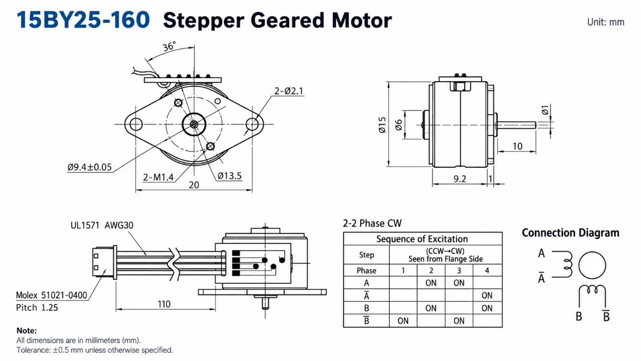
20mm

25mm

35mm

42mm
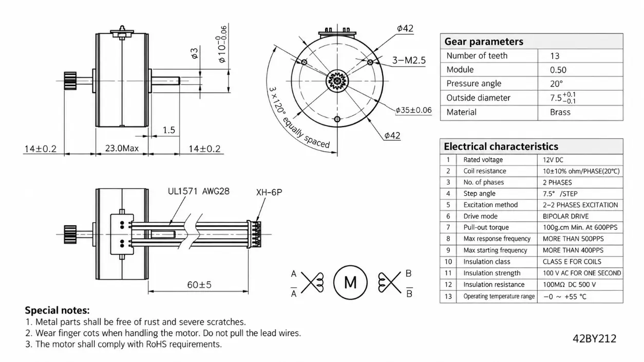
The comparison also shows why miniature stepper is not one fixed technical class. An 8 mm PM stepper and a 42 mm hybrid stepper are both stepper motors, but they do not share the same shaft capability, mounting format, winding space, bearing arrangement, or suitable load range. The smallest stepper motor should therefore be selected against the actual mechanism rather than against a diameter chart alone.
Why Going Smaller Can Increase Integration Difficulty
A smaller motor is not automatically easier or cheaper to integrate. When a design is pushed toward the smallest stepper motor that can physically fit, the available space for the electromagnetic and mechanical structure becomes tighter. Manufacturing tolerances, shaft geometry, wire routing, connector placement, and mounting clearances can become more sensitive to the surrounding assembly.
The engineering relationship is better described as a conditional chain rather than an absolute rule:
Smaller motor diameter
↓
less cross-sectional space for windings and magnetic components
↓
changes in available torque capability
↓
less room for shaft support, bearings, wires, and connectors
↓
tighter mechanical and thermal constraints
↓
greater sensitivity to the final application
Motor length still matters. A smaller-diameter motor can use a longer body or a different internal design, so diameter alone does not determine total winding volume or output capability. The practical effect is that engineers must compare complete motor geometry and performance data rather than assuming that every smaller motor has proportionally lower output.
Wire routing is a simple example. The motor body may clear the enclosure, yet the connector or lead-wire bend radius may interfere with a nearby housing wall. In a very small assembly, a few millimeters of extra space can determine whether the wiring can be installed without excessive bending or assembly stress.
In some designs, choosing a slightly larger standard motor may reduce integration complexity in the shaft, mounting, wiring, or assembly system. This does not mean that a larger motor is always preferable. It means that total system fit should be evaluated together with motor diameter.
The Torque Trade-Off Behind the Smallest Stepper Motor
Torque is often one of the primary performance constraints when motor size is reduced. Reducing motor diameter generally limits the cross-sectional space available for stator windings, magnetic components, rotor geometry, shaft support, and thermal design. At the same time, motor length, current, winding design, magnetic circuit design, and internal construction can change the final result. A smaller diameter therefore does not create one fixed torque value.
For the smallest stepper motor, engineers should avoid comparing products with only one torque figure. Holding torque is the static torque available when the motor is energized at the specified current and the rotor is stationary. It does not represent the torque available at every running speed.
Pull-in and pull-out characteristics, when provided by the motor manufacturer, give additional information about dynamic operation. Pull-out torque is particularly useful when evaluating whether the motor can continue operating at a required stepping rate and load. Detent torque is different again: it describes the resisting torque present when the motor is not energized.
Consider a positioning mechanism that accelerates a small lead screw. A motor may show an adequate holding torque on the datasheet, but the available running torque can fall as step rate increases. The correct selection question is whether the smallest stepper motor provides sufficient torque at the required operating speed with suitable margin for friction, acceleration, and load variation.
A gearbox can increase output torque and reduce output speed, but the transmission introduces additional parameters such as reduction ratio, backlash, efficiency, gearbox length, output-shaft load, and transmission losses. Gearbox output torque should not be treated as bare motor torque.
Shaft, Bearings, Wiring, and Mounting Become Critical at Small Sizes
Motor diameter often receives most of the attention during early mechanical design, but a small size stepper motor must fit after the shaft, wires, connector, fasteners, gearbox, or lead screw are included. The motor housing is only one part of the installation envelope.
In very small motor packages, the available geometry can limit practical shaft and bearing dimensions. Shaft diameter and exposed shaft length must be checked against the way the motor is loaded. A pinion, pulley, cam, coupling, or lead screw can introduce radial or axial forces that are not visible from the motor diameter alone.
A smallest stepper motor may have enough electromagnetic capability for the application while still being unsuitable because the required shaft is too large, too long, or subject to excessive load. D-shafts, flats, threaded shafts, pinion gears, and other interfaces must therefore be treated as part of the motor selection process.
Wiring creates another limit. In a tiny stepper motor, lead wires and connectors can occupy a meaningful portion of the available mechanical envelope. Equipment designers should verify the wire-exit direction, connector dimensions, bending clearance, and nearby structural parts before releasing the mounting design.
Mounting hole spacing, pilot features, screw size, shaft center position, body length, rear clearance, and neighboring components should be reviewed together. A motor that fits by diameter can still be impossible to assemble if one of these interfaces conflicts with the equipment.
PM Stepper Motor vs Smallest NEMA Stepper Motor


The smallest stepper motor and the smallest nema stepper motor refer to different engineering questions. A permanent magnet stepper can use a round housing whose dimensions are defined by the motor design. A NEMA hybrid stepper belongs to a standardized frame and mounting family.
NEMA 8, NEMA 11, NEMA 14, and NEMA 17 indicate progressively larger frame families, approximately corresponding to 20, 28, 35, and 42 mm class frame dimensions. The NEMA designation does not define one universal voltage, current, holding torque, speed, shaft length, or motor body length.
Two motors using the same NEMA frame can have different stack lengths, windings, rated currents, holding torques, shafts, and electrical characteristics. For this reason, selecting a NEMA motor only by frame number can create the same type of error as selecting a PM motor only by diameter.
The distinction is particularly important around similar dimensions. A 35 mm PM stepper is not automatically a NEMA 14 motor, and a 42 mm PM stepper is not automatically a NEMA 17 motor. The mounting structure and motor construction must support the classification.
NEMA 8 can be considered when the project requires a relatively small hybrid frame and standardized mounting geometry. A physically smaller PM design may be more appropriate where available diameter is the dominant constraint. The smallest stepper motor is therefore not necessarily the same product as the smallest standardized NEMA option.
When an 8–10 mm Stepper Motor Makes Sense


An 8 mm or 10 mm motor can be considered when the installation diameter is highly restricted and the mechanical load is compatible with the selected design. Possible applications include small optical positioning mechanisms, camera mechanisms, miniature valves, medical-device mechanisms, laboratory automation modules, and other small actuators where installation space is limited.
These are possible application categories rather than claims that every 8 mm or 10 mm motor is suitable for each use. The actual smallest stepper motor must still be checked against torque, operating speed, shaft load, duty cycle, temperature, driver conditions, and mechanical life requirements.
Moving from an 8–10 mm tiny stepper motor to a 15–28 mm motor may be more practical when the application needs a larger shaft, greater bearing support, higher running torque, gearbox integration, lead-screw integration, more wiring space, or a different mounting arrangement.
The engineering mistake is to select the minimum diameter first and then attempt to force all performance requirements into that package. The required load and installation conditions should define the acceptable size range before a specific motor is selected.
How to Choose the Smallest Suitable Stepper Motor
A structured selection process helps prevent an undersized smallest stepper motor from reaching the prototype stage before its limitations are discovered.
- Define maximum motor diameter. Use the actual available installation envelope rather than only the nominal enclosure width.
- Define maximum motor length. Include the shaft, rear wiring, connector, gearbox, lead screw, and other attached components where applicable.
- Define the mechanical load. Consider friction, acceleration, external forces, transmission losses, and the direction of the load.
- Define operating speed. Evaluate torque at the required stepping rate rather than relying only on static holding torque.
- Confirm positioning requirements. Check step angle, travel per step, required repeatability, transmission ratio, or lead-screw pitch as applicable.
- Specify the shaft interface. Define diameter, exposed length, flat, thread, pinion, coupling, or lead-screw requirements.
- Confirm electrical conditions. Match the selected winding to the available supply, driver current, drive method, and control requirements.
- Check wires and connectors. Verify wire-exit direction, connector size, strain relief, and bending space.
- Evaluate transmission requirements. If a gearbox or lead screw is needed, include ratio, output speed, backlash, load, stroke, and total assembly length.
- Compare the next larger size. A modest increase in diameter can provide additional mechanical or torque margin and may simplify integration.
The correct smallest stepper motor is normally the smallest configuration that satisfies these requirements with sufficient engineering margin, not simply the smallest unit that can be inserted into the housing.
Kechen Motor Small Stepper Motor Size Options
Kechen Motor supplies small stepper motor solutions for OEM equipment and industrial projects. Available structures include permanent magnet stepper motors, hybrid stepper motors, geared stepper motors, and linear or lead-screw stepper configurations.
For projects evaluating the smallest stepper motor, Kechen Motor product families can cover size classes including 8 mm, 10 mm, 15 mm, 20 mm, 25 mm, 28 mm/NEMA 11, 35 mm, and 42 mm, depending on the motor structure and project requirements.
The product relationship can be considered as:
Small Stepper Motor
→ Permanent Magnet Stepper Motor
→ Hybrid Stepper Motor / NEMA Size
→ Geared Stepper Motor
→ Linear Stepper Motor
Configuration changes can include winding or voltage selection, shaft geometry, lead wires, connectors, gearbox integration, lead screws, and mounting arrangements where the selected motor platform supports them. These options should not be assumed to be available for every motor diameter.
Specifications are for reference only. Final parameters should be confirmed based on approved samples and project requirements.
What to Send When Requesting the Smallest Suitable Motor
An engineering inquiry for the smallest stepper motor should contain more than a target diameter. Useful information includes the maximum motor diameter, maximum body length, available voltage, required operating speed, torque or mechanical load, step angle or positioning requirement, shaft dimensions, wire direction, mounting limits, application, and duty cycle.
If the mechanism uses a gearbox, provide the required output speed, torque, or gear ratio where known. If linear motion is required, include the lead-screw specification, travel, required linear speed, stroke, and axial load where available. Estimated quantity also helps determine whether a standard motor or a modified configuration is more appropriate.
An installation drawing or dimensional envelope is especially useful because it allows the motor body, shaft, connector, wire exit, fasteners, gearbox, and lead screw to be reviewed as one assembly. This reduces the risk of selecting a smallest stepper motor that meets the diameter limit but conflicts with another mechanical feature.
Conclusion
The most useful smallest stepper motor is not the lowest diameter available, but the smallest size that still meets the required running torque, positioning, shaft support, wiring, mounting, and operating conditions of the real mechanism.
FAQ
What Is the Smallest Stepper Motor Size?
There is no universal minimum size for every application. Commercial PM stepper motors are available in diameters as small as 8 mm, but this does not mean that 8 mm is the absolute smallest stepper motor in the world. The minimum practical size depends on torque, operating speed, motor length, shaft dimensions, winding, mounting, wiring, and application load. A physically smaller motor may exist but still be unsuitable for the required mechanism.
Does a Smaller Stepper Motor Always Produce Less Torque?
No. Diameter alone does not define torque. Motor length, magnetic circuit design, winding configuration, current, rotor structure, and operating speed also influence performance. However, reducing diameter generally restricts the cross-sectional space available for the electromagnetic and mechanical structure. For a smallest stepper motor, torque should therefore be checked at the required operating speed rather than estimated from diameter or holding torque alone.
What Is the Smallest NEMA Stepper Motor?
NEMA 8 is one of the smaller standardized hybrid stepper frame families used in space-limited systems. It should not be treated as the minimum physical size for all stepper motors because PM stepper motors can use smaller round housings that do not follow NEMA frame dimensions. When comparing a smallest nema stepper motor with a PM design, check mounting format, body dimensions, shaft configuration, torque-speed requirements, electrical conditions, and available installation space rather than frame terminology alone.