

Micro Motor Blogs
12V Stepper Motor Selection for the Right Voltage and Current Match
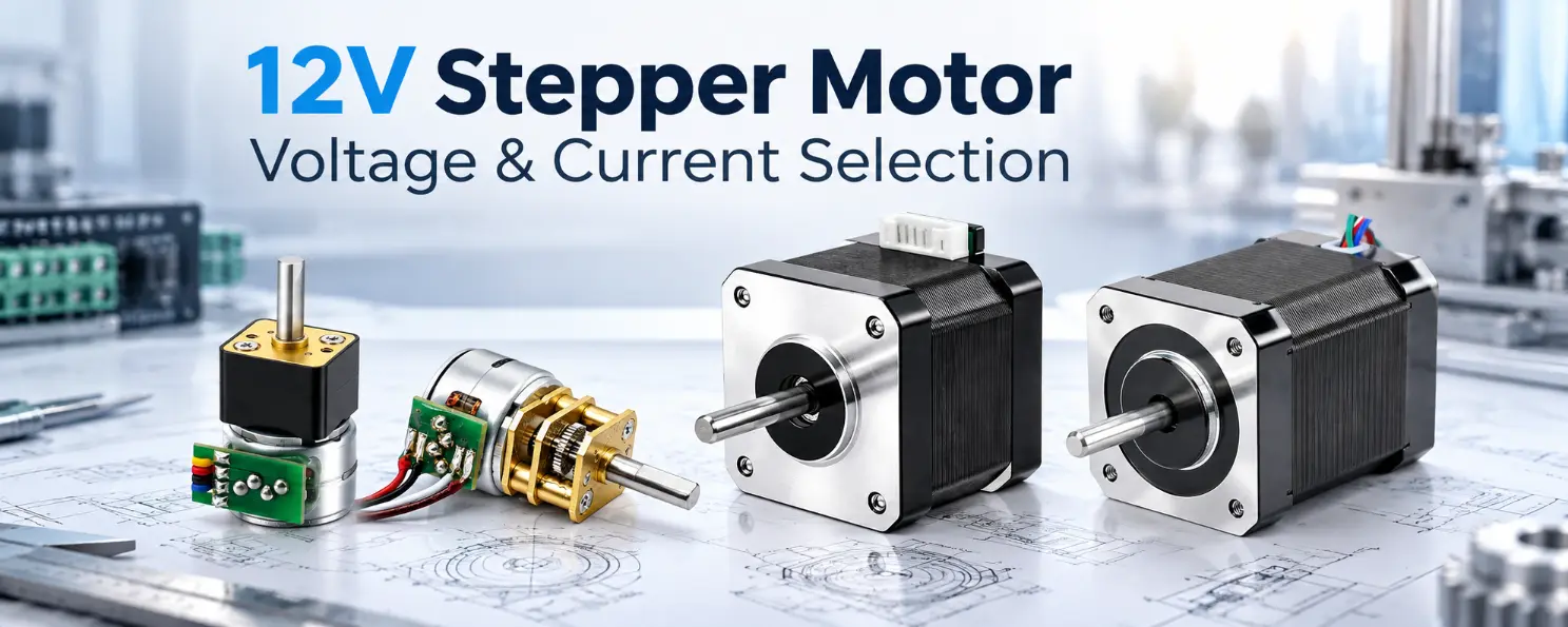
Selecting a 12V stepper motor requires more than matching the voltage printed on a motor label to an available power supply. In industrial positioning equipment, a mismatch between motor winding characteristics, driver current settings, and supply voltage can lead to excessive heating, missed steps, or insufficient torque during acceleration. The motor winding rated voltage, stepper driver input voltage, and DC power supply voltage are separate specifications. They are related, but they do not always need to be identical.
The correct electrical arrangement depends on winding resistance, phase current, inductance, driver current regulation, and the required torque at operating speed. A permanent magnet (PM) stepper motor may also have different control requirements from a hybrid stepper motor. Understanding these distinctions is necessary before selecting a motor, driver, or power supply for automated equipment.
What Does 12V Mean on a 12V Stepper Motor?
The voltage shown in a motor specification does not necessarily describe the voltage required by the complete drive system. For a 12V stepper motor, the meaning depends on the manufacturer’s winding specifications and intended control method.
Engineers should distinguish three electrical values before approving a motor-driver combination: winding rated voltage, driver input voltage, and external power supply voltage.
Motor Winding Rated Voltage
Winding rated voltage is associated with the electrical characteristics of a particular motor winding under defined conditions. In a steady-state DC circuit, voltage, resistance, and current are related by Ohm’s law:
For illustration, an idealized winding with a resistance of 24 Ω would draw 0.5 A from a continuous 12 V DC supply at steady state, producing approximately 6 W of resistive heating. These calculated values are examples rather than specifications for a particular motor.
Actual winding resistance changes with temperature. During stepping, inductance, back electromotive force (back EMF), switching behavior, and driver regulation also affect current. Consequently, the simple resistance calculation does not establish a motor’s running torque, temperature rise, or allowable duty cycle.
Stepper Driver Input Voltage
The driver receives electrical power and controls the excitation of the motor phases. A current-regulated driver uses switching control to manage winding current according to its configured current reference and operating mode.
A motor with a relatively low winding voltage can therefore operate from a higher driver supply voltage when the driver is designed for that arrangement and current is regulated within the motor’s permitted limits. This does not mean that any higher voltage can be applied without checking driver specifications.
External DC Power Supply Voltage
The power supply provides electrical energy to the drive system. In a laboratory instrument, for example, a 12 V distribution rail may supply a motion controller and several electronic assemblies. The stepper driver’s input voltage can be 12 V while the connected motor has a different nominal winding voltage.
A 12v dc stepper motor should therefore be evaluated using its actual winding specifications and the intended driver rather than the voltage of the available power supply alone.
Matching Voltage and Current in a 12V Stepper Motor
Phase current is a central electrical parameter when selecting a 12V stepper motor. It affects the magnetic field produced by the motor windings and contributes to the torque developed during operation. However, the relationship between current and torque is not unlimited or necessarily linear across the complete operating range.
Increasing phase current may improve available torque within the motor’s specified operating limits, but copper losses also increase. Excessive current can raise winding temperature and transfer heat into nearby components. This is particularly relevant for enclosed optical mechanisms, medical instrument assemblies, and small motor housings with restricted airflow.
Insufficient phase current creates a different problem. A motor may rotate successfully during unloaded testing but lose synchronism when accelerating a mechanism or overcoming a change in friction. The motor’s available dynamic torque must exceed the mechanical torque demand with an appropriate engineering margin.
The electrical values below should be reviewed together rather than independently.
| Electrical Parameter | Engineering Meaning | Selection Consideration |
|---|---|---|
| Rated Winding Voltage | Voltage associated with the specified winding and operating conditions | Confirm the manufacturer’s voltage definition and intended drive method |
| Rated Phase Current | Specified operating current for a motor phase under defined conditions | Compare with motor and driver current limits |
| Winding Resistance | Electrical resistance of the motor winding | Influences resistive voltage drop and copper losses |
| Winding Inductance | Electrical characteristic that resists changes in winding current | Influences current response and high-speed behavior |
| Driver Current Setting | Current reference or limit configured in the driver | Verify peak-current and RMS-current conventions |
| Supply Input Current | Current drawn by the driver from the external power source | Must not automatically be equated with motor phase current |
For current-regulated systems, the driver’s phase-current setting should be checked against the motor manufacturer’s rated current and the driver’s peak-current or RMS-current convention. A nominal current value on the driver cannot be interpreted correctly without knowing how that value is defined.
Consider an automated dispensing mechanism in which the drive load increases as material resistance changes. The motor may move correctly during initial testing but miss steps under higher resistance. Before increasing current, the engineer should review the acceleration profile, torque requirement, motor temperature, and available torque at the intended operating speed.
For a 12 volt dc stepper motor, electrical compatibility should be established from the motor datasheet and driver specifications rather than a nominal voltage designation.
Why a Stepper Driver Changes Voltage Matching
How Current-Regulated Drivers Work
A current-regulated stepper driver adjusts its switching output to control current through the motor windings. Instead of relying entirely on the supply voltage and winding resistance, the driver attempts to follow a configured current reference within its electrical operating limits.
For a 12V stepper motor, this means the motor’s nominal winding voltage and the driver’s DC input voltage do not necessarily need to match. The driver must still support the required input voltage, current regulation range, winding connection, and control sequence.
Current settings also require careful interpretation. Some drivers specify peak phase current, while others describe RMS current or a reference associated with a particular stepping mode. Applying the same numerical setting across different current definitions can produce different winding currents and heating conditions.
Winding Inductance and Current Rise
Stepper motor windings are inductive electrical loads. Inductance resists rapid current changes, making current rise time important as the stepping frequency increases.
At low stepping frequencies, the winding may have sufficient time to approach the commanded phase current. At higher frequencies, the available time becomes shorter, and the current may not reach its intended level before the next electrical transition.
In a suitable current-regulated system, a higher driver supply voltage can provide additional voltage headroom for changing winding current. This may improve available torque at higher speeds, depending on winding inductance, resistance, back EMF, current decay behavior, driver control, and mechanical load.
For example, an instrument positioning axis may require repeated movement between locations at a defined acceleration rate. Increasing supply voltage within the driver’s permitted range may improve current response, but the result must be verified against the motor’s actual torque-speed characteristics.
Checking Driver Compatibility
Driver selection should begin with its supported DC input voltage range and phase-current capability. The motor’s wiring configuration, excitation method, and operating current must then be checked against the driver’s supported output arrangement.
Current ripple, switching behavior, and thermal capacity may also affect performance. A driver that supports the required voltage numerically is not necessarily suitable for every winding or operating condition.
The engineering objective is to establish a compatible motor-driver combination, not simply to match voltage labels.
PM Stepper Motors vs Hybrid Stepper Motors
Permanent magnet and hybrid stepper motors use different electromagnetic constructions. Although both can provide controlled incremental rotation, their winding arrangements, mechanical characteristics, and intended control methods may differ.
12V Permanent Magnet Stepper Motor
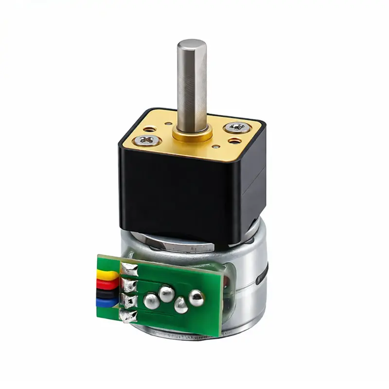
Permanent magnet stepper motors are used in positioning mechanisms, valve actuators, optical assemblies, and instrument control systems. Selection commonly involves motor diameter, winding specifications, step angle, mechanical output requirements, and available mounting space.
When evaluating a PM 12V stepper motor, engineers should review phase resistance, rated voltage, current, step angle, motor dimensions, and shaft configuration. The required drive method should also be established before selecting a controller.
PM stepper motors may use voltage-driven or current-regulated control depending on their winding design and intended application. Driver compatibility depends on phase count, unipolar or bipolar wiring, winding resistance, rated phase current, controller topology, and excitation sequence.
For a valve actuator, a geared PM stepper may be considered when the output requires lower rotational speed and increased torque. A gearbox changes the output relationship between motor speed and torque, but gearbox efficiency, backlash, permissible loading, and duty cycle must also be evaluated.
Where linear displacement is required, a lead screw arrangement may be considered. The screw lead, mechanical efficiency, axial loading, and available travel determine whether the assembled actuator can meet the application requirements.
12V Hybrid Stepper Motor
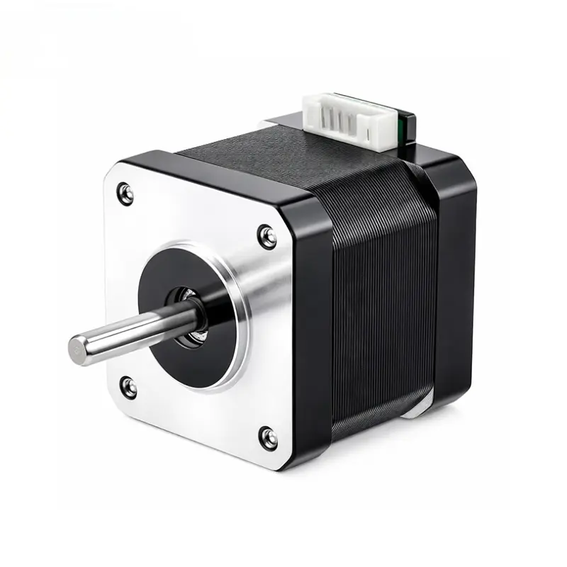
Hybrid stepper motors combine permanent magnet and toothed rotor features. Their selection commonly considers frame size, phase current, winding resistance, inductance, step angle, holding torque, and torque-speed performance.
Many hybrid stepper systems use current-regulated drivers. The driver supply voltage and phase-current settings should therefore be selected according to the motor’s electrical characteristics and the required operating point.
Holding torque describes resistance to rotation while the motor is energized and stationary under specified conditions. It does not represent the torque available during continuous rotation at a particular speed.
For a positioning stage that repeatedly accelerates a mechanical load, the torque-speed curve and acceleration requirement provide more useful selection information than holding torque alone.
What NEMA 17 12V Actually Specifies
The search expression nema 17 12v is often associated with hybrid stepper motors, but NEMA 17 primarily identifies a nominal 1.7-inch frame-size family. It does not establish a universal winding voltage, current rating, inductance, or holding torque.
Two NEMA 17 motors may share similar mounting dimensions while having different winding resistance, current requirements, shaft configurations, and torque-speed performance.
An approximately 42 mm permanent magnet stepper motor should not automatically be classified as NEMA 17. The motor construction and actual frame and mounting specifications must be confirmed.
When replacing an existing motor, engineers should verify both mechanical interchangeability and electrical compatibility. Matching the frame designation alone does not establish equivalent performance.
12V vs 24V Stepper Motor Systems
A 12v vs 24v stepper motor comparison must distinguish motor winding ratings from driver supply voltage. A system operating from a 24 V power supply does not necessarily contain a motor with a 24 V-rated winding.
For a 12V stepper motor operating with a compatible current-regulated driver, increasing the supply voltage may improve the rate at which winding current changes. This can influence torque availability at higher stepping frequencies, provided the driver’s electrical limits and the motor’s thermal requirements are respected.
The comparison below assumes the same motor is operated using a compatible current-regulated driver at two permitted supply voltages, with otherwise comparable current settings and operating conditions. Actual results depend on motor winding properties, driver control behavior, speed, and mechanical loading.
| Selection Factor | 12 V Driver Supply | 24 V Driver Supply |
|---|---|---|
| Current Rise | Less available voltage headroom under otherwise comparable conditions | Greater voltage headroom may support faster current changes |
| High-Speed Torque | Current rise may become limiting at lower speeds | May help maintain commanded phase current at higher speeds |
| Low-Speed Operation | May already provide sufficient current regulation | May offer limited additional torque benefit if the required current is already achieved |
| Driver Requirements | Requires compatible input voltage and current settings | Requires compatible input voltage and current settings |
| System Integration | May use an existing 12 V supply | Requires a compatible 24 V power source and driver |
| Engineering Validation | Confirm torque-speed performance, thermal behavior, and electrical compatibility | Confirm torque-speed performance, thermal behavior, and electrical compatibility |
At low stepping frequencies, the torque difference may be small if both driver configurations can establish the commanded winding current. Current ripple, control mode, resonance, and motor characteristics can still influence the result.
At higher stepping frequencies, winding inductance and back EMF may restrict current development. Under these conditions, additional driver supply voltage can be useful, but the improvement cannot be quantified without actual motor-driver performance data.
Higher supply voltage may also affect switching losses, current ripple, electromagnetic interference, and driver temperature. A 24v stepper motor system is therefore not automatically preferable to a 12 V system.
For a low-speed instrument actuator, an existing 12 V supply may already meet the required operating conditions. A higher-speed positioning axis may have different requirements. The decision should follow the actual torque-speed demand and available electrical architecture.
How to Select the Right 12V Stepper Motor for an Engineering Project
Electrical selection should begin with the mechanical application. A motor that satisfies the nominal voltage requirement may still be unsuitable if it cannot produce sufficient torque at the required speed or if its winding characteristics exceed the available driver’s capabilities.
1. Determine the Mechanical Load
Define the required torque, operating speed, acceleration, load inertia, and expected friction. The motor must supply enough dynamic torque to accelerate the mechanism and overcome its working resistance.
For a lead screw-driven laboratory mechanism, axial force and travel speed should be established before motor torque is calculated. Screw lead, mechanical efficiency, friction, and the transmission arrangement affect the relationship between rotary torque and linear force.
Available installation dimensions, shaft requirements, mounting tolerances, and mechanical interfaces should also be documented.
2. Choose the Motor Construction
Select permanent magnet or hybrid stepper technology according to the required electrical and mechanical characteristics. Geared stepper configurations may be considered for lower-speed output with greater available torque, while lead screw stepper configurations may be suitable for applications requiring controlled linear movement.
The chosen construction should reflect the operating requirements rather than the availability of a motor carrying a particular voltage designation.
3. Review Winding Characteristics
Check the motor’s rated winding voltage, rated phase current, winding resistance, inductance where available, phase count, and wiring configuration. Confirm whether the specified electrical conditions assume voltage-driven operation or current regulation.
These distinctions are important because a 12v dc stepper motor may have different electrical control requirements from another motor with a similar nominal voltage.
4. Select a Compatible Stepper Driver
Confirm that the driver supports the external supply voltage, required phase current, and motor wiring arrangement. Review its current-setting method, supported excitation modes, control interface, and thermal operating limits.
Where microstepping is used, distinguish commanded positioning resolution from actual mechanical accuracy. Microstepping can improve motion smoothness and increase the number of commanded positions per revolution, but friction, load torque, driver regulation, and mechanical backlash still influence positioning error.
5. Verify Power Supply Capacity
Confirm the driver’s permitted input voltage, expected supply current, operating duty cycle, and available thermal margin. The supply must support the driver and any other connected electrical loads under the intended operating conditions.
Motor phase current must not be confused with the average DC current drawn by a switching driver. Supply input current depends on the driver’s power conversion behavior, efficiency, motor operating conditions, and energized phase currents.
6. Validate the Complete Assembly
Test the selected 12V stepper motor with its intended driver, supply voltage, mechanical load, and acceleration profile. Where measured torque-speed data is available, verify that the motor provides sufficient torque margin at the required operating speed.
Operating-temperature measurements should be made under representative duty conditions. Check for missed steps, excessive vibration, driver overheating, and changes in motion behavior as the load varies.
Final parameters should be confirmed using approved samples and the actual project requirements.
Common 12V Stepper Motor Selection Mistakes
Several electrical and mechanical selection errors can affect system reliability even when the motor appears compatible with the available power supply.
- Matching voltage labels without checking phase current: The resulting driver settings may not suit the selected motor winding.
- Ignoring winding inductance: Current may not develop sufficiently at higher stepping frequencies, reducing available running torque.
- Assuming all NEMA 17 motors have equivalent windings: Similar frame dimensions do not guarantee the same electrical characteristics.
- Confusing holding torque with running torque: A stationary torque specification does not establish torque at operating speed.
- Using an incompatible driver topology: PM and hybrid motors may have different phase and wiring requirements.
- Misinterpreting driver current ratings: Peak-current and RMS-current values should not be exchanged without checking the manufacturer’s definitions.
- Ignoring acceleration and load inertia: A motor with sufficient steady-speed torque may still lose synchronism during acceleration.
- Skipping representative thermal testing: Short operating tests may not reveal temperature conditions during repeated or continuous duty.
For a 12V stepper motor in industrial automation, these checks help establish whether the complete drive system can meet the intended mechanical and electrical requirements.
Information to Send a Stepper Motor Manufacturer Before Selection
A technical inquiry should describe the operating conditions rather than providing only a nominal voltage or motor frame designation. This allows the supplier to evaluate motor structures and available configurations against the actual application.
When requesting a 12V stepper motor quotation or sample, engineers and purchasing teams should provide the following information where available:
- Motor type: permanent magnet or hybrid stepper
- Available DC power supply voltage
- Required winding voltage or existing motor specifications
- Rated phase current and winding resistance
- Winding inductance, if known
- Required operating speed and torque at that speed
- Step angle and positioning requirements
- Motor diameter, frame size, length, and mounting dimensions
- Shaft dimensions, gearbox ratio, or lead screw requirements
- Existing driver model, input voltage, and current settings
- Application, duty cycle, and operating environment
- Estimated order quantity
Kechen Motor, operated by Shenzhen Kechen Micro Motor Technology Co., Ltd., supplies micro motors and OEM/ODM motor solutions for engineering applications. Project requirements involving winding specifications, shaft arrangements, gearbox options, lead screw configurations, and connectors can be reviewed according to the selected motor platform and engineering feasibility.
Available configurations and customization requirements should be confirmed through product specifications, drawings, and sample evaluation. Not every electrical or mechanical combination is necessarily available across all motor structures.
For motor configuration review, provide your required voltage, phase current, operating speed, torque, motor dimensions, mechanical interface, driver information, application, and estimated order quantity to Kechen Motor.
Conclusion: Match the Motor, Driver, and Load
Selecting a 12V stepper motor requires matching winding characteristics, phase-current control, driver supply voltage, and available torque at the intended operating speed rather than relying on nominal voltage alone.
Frequently Asked Questions
Can I Connect a 12V Stepper Motor Directly to a 12 V Power Supply?
Applying 12 V directly to a winding is appropriate only when its electrical specifications and intended control method permit it. A 12V stepper motor also requires a suitable phase-excitation sequence for controlled rotation. Applying voltage without checking winding resistance, rated current, and drive requirements can produce excessive heating. Current-regulated drivers are commonly used when winding current must be actively controlled.
Does a 12V DC Stepper Motor Always Require a 12 V Driver?
No. Motor winding voltage and driver input voltage are different specifications. A suitable current-regulated driver may use a supply voltage higher than the motor’s nominal winding voltage, provided the driver supports the arrangement and phase current remains within the motor’s permitted limits. The motor’s wiring configuration, driver current regulation, and thermal conditions must also be checked.
Is a 24 V Supply Better Than 12 V for Every Stepper Motor?
No. A higher driver supply voltage may improve current rise and high-speed torque in certain current-regulated systems, but it does not automatically increase holding torque or improve every operating condition. Winding inductance, driver limits, current settings, speed, and mechanical loading determine the result. A 12V stepper motor system should be evaluated using its required torque-speed operating point and verified electrical conditions.