

Micro Motor Blogs
5 Common Integration Pitfalls When Using Small Stepper Motors in Consumer Electronics
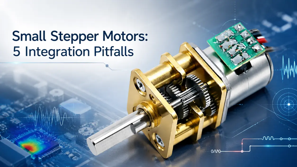
The increasing adoption of space-constrained automated consumer electronics—such as automated surveillance dome cameras, handheld smartphone gimbals, and portable insulin pumps—places significant demands on electromechanical designers. Integrating small stepper motors (the core focus of this guide) into tight internal architectures requires balancing strict spatial allocations with dynamic performance. Overlooking critical hardware and firmware integration aspects frequently leads to extended development cycles and premature field failures.
Pitfall 1: Ignoring Thermal Management in Sealed Housings
Consumer devices frequently lack active cooling mechanisms, relying entirely on passive dissipation through plastic enclosures. When a small size stepper motor, such as those embedded in motorized security cameras, maintains a continuous holding current to lock position, Joule heating generates localized thermal concentrations inside closed chambers. This temperature escalation induces rotor demagnetization, warps internal polyoxymethylene gear trains, and triggers thermal shutdown in nearby driver integrated circuits.
To mitigate this operational risk, developers must implement software‑driven dynamic current reduction during idle states, alongside optimizing printed circuit board copper ground planes to function as passive heat sinks. Thermal dissipation limits must be validated early using infrared thermography during continuous stall testing.
Pitfall 2: Overlooking Microstepping Resolution and Vibration
Driving miniature stepper motors at coarse full‑step or half‑step configurations often introduces high levels of acoustic noise and mechanical resonance. In audio‑adjacent applications like smart conference speaker tracking modules, audible buzzing degrades user experience, while in optical zoom lenses, resonance causes jerky image shifts. Operating a micro stepper motor without appropriate sinusoidal current commands exacerbates stepping non‑linearities and torque ripple.
Engineers should upgrade driver integrated circuits to support advanced microstepping (up to 1/256 step) and configure mixed‑decay modes correctly to suppress current ripple and smooth motion profiles. Furthermore, miniature stepper motors require careful tuning of decay parameters to match electrical time constants, preventing high‑frequency current chopping from overheating the motor windings.
Pitfall 3: Underestimating Power Supply Voltage and Current Drops
Powering motion control stages directly from low‑voltage USB rails or unregulated single‑cell lithium‑ion batteries without sufficient voltage headroom severely degrades dynamic capability. For instance, in handheld barcode scanners utilizing a small high torque stepper motor, sudden load spikes cause significant voltage sag across thin internal PCB traces. This sag results in severe torque reduction at higher rotational speeds, missed steps, and unexpected microcontroller resets due to rail collapse.
A robust design separates the logic power rail from the motor power supply, integrates dedicated step‑up switching regulators, and places low‑ESR bulk ceramic capacitors immediately adjacent to the motor driver input pins to absorb transient current surges and maintain stable bus voltage.
Pitfall 4: Mechanical Misalignment and Rigid Shaft Coupling
Enforcing rigid mechanical tolerances without accommodating microscopic assembly shifts introduces destructive forces into electromechanical assemblies. In automated medical diagnostic pipetting instruments, direct rigid coupling between the motor shaft and lead screw places excessive radial and axial side‑load stress on delicate miniature bearings. Over time, this friction accumulation leads to premature bearing wear and complete shaft binding.
Utilizing flexible micro‑couplings and verifying coaxial alignment during prototype assembly resolves these structural stresses. The table below outlines key technical parameters that must be evaluated against mechanical load constraints during the selection phase.
| Parameter Specification | Standard Rating Range | Critical Integration Impact |
|---|---|---|
| Holding Torque | 0.5 mNm to 50 mNm | Determines payload capacity against gravitational and inertial loads. |
| Rotor Inertia | 0.1 g·cm² to 5.0 g·cm² | Affects acceleration rates and resonance frequency thresholds. |
| Step Angle Tolerance | ±5% (Non‑cumulative) | Directly influences open‑loop positioning accuracy over multi‑turn rotations. |
| Maximum Axial Load | 1.0 N to 10.0 N | Exceeding this threshold damages internal thrust bearings. |
Pitfall 5: Relying Solely on Open‑Loop Control Without Stall Handling
Assuming that a stepper motor will consistently track positional commands without feedback when physical obstructions occur introduces critical vulnerabilities. In automated robotic vacuum cleaner brush height adjusters, encountering an unexpected floor obstacle causes the motor to stall while the driver continues to pulse current, leading to excessive power dissipation and stripped internal gear teeth.
When utilizing the smallest nema stepper motor in tight layouts, developers must implement back‑electromotive‑force stall detection routines or integrate secondary magnetic encoders to maintain closed‑loop verification and protect hardware integrity against unexpected mechanical blocks.
Conclusion
Successfully embedding the smallest stepper motor into modern consumer electronics demands a systematic design approach that strictly balances spatial boundaries, thermal dissipation profiles, and electrical parameter margins during the initial prototyping phase. OEM design teams seeking efficient development cycles can leverage custom winding adjustments and shaft modifications to match specific application constraints. Requesting factory evaluation samples and consulting comprehensive technical documentation accelerates prototype validation and ensures reliable mass‑production performance.
Frequently Asked Questions (FAQ)
Does increasing microstepping resolution linearly increase positional accuracy?
No. While high microstepping resolutions (such as 1/256 step) significantly reduce acoustic noise and smooth out mechanical resonance, mechanical accuracy remains fundamentally bounded by the inherent step angle tolerance of the motor and external load friction, rather than electrical subdivision alone.
Can holding current be reduced to zero during idle states without losing position?
Reducing holding current to zero eliminates holding torque entirely. In applications where external loads or gravitational forces act upon the axis, such as a vertical lifting mechanism in an automated analytical analyzer, zero current will cause positional slippage unless a mechanical brake or self‑locking lead screw is present.