180 Motor Series with 20mm Metal Spur Gearbox, D-Shaped Shaft and 3V–24V
Related Product Documents & Downloads
| Document Description | File Details |
|---|---|
| KC-GM20-FK-180SH-00781 12V Brushed DC Gear Motor Drawing & Performance Curve |
PDF · English · 215 KB |
KC-GM20-180SH 180 Motor With 20 mm Metal Gearbox
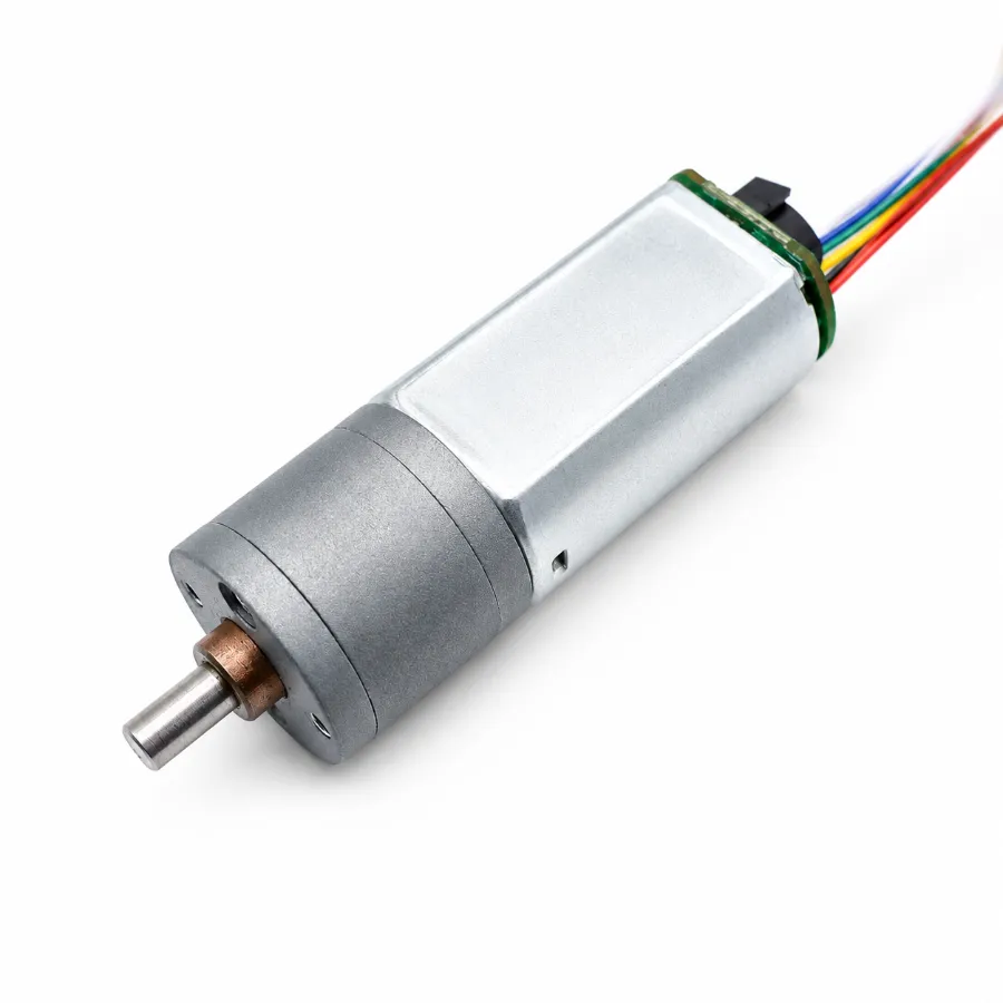
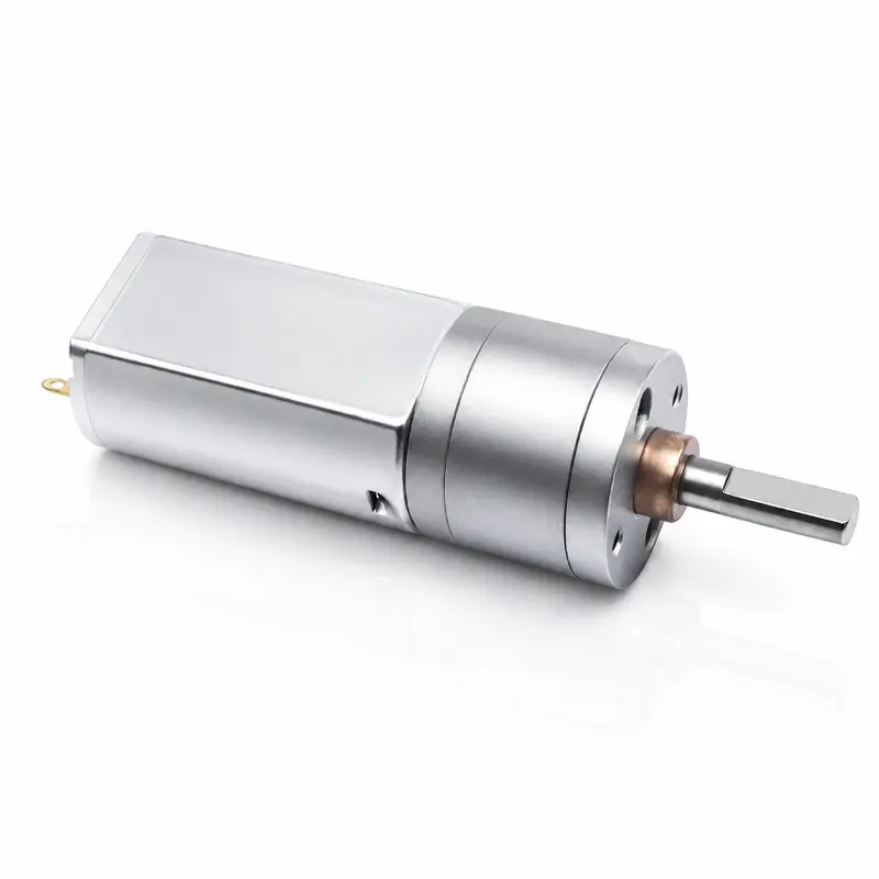
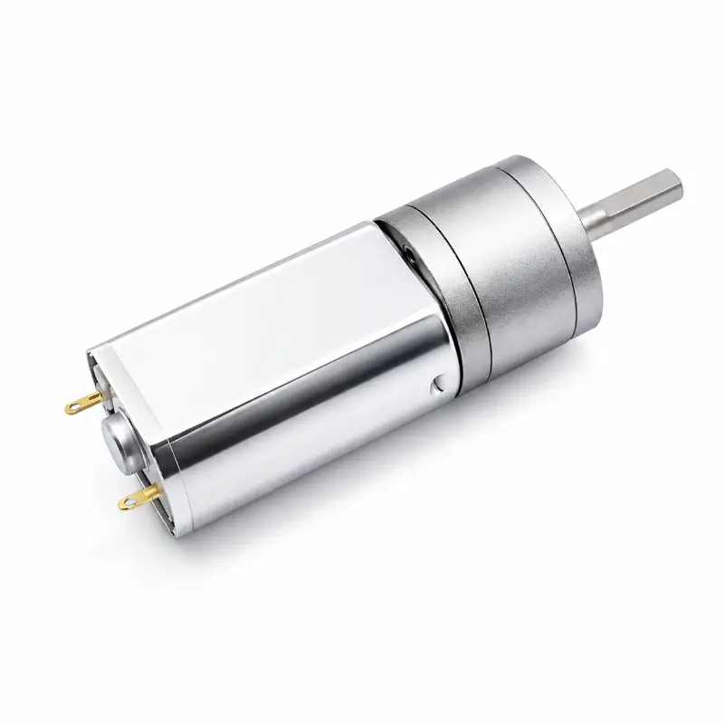
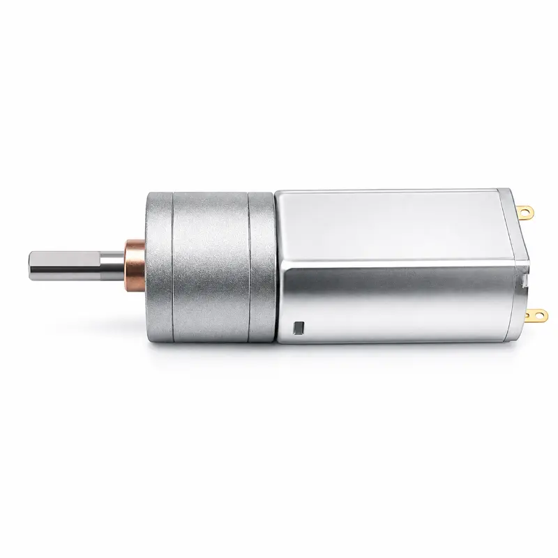
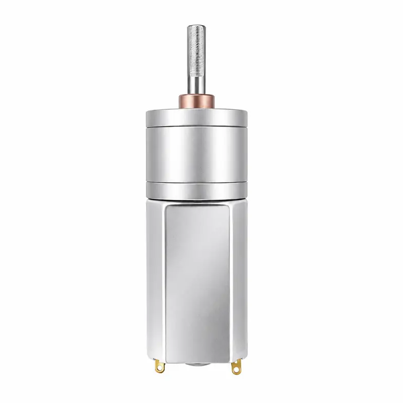
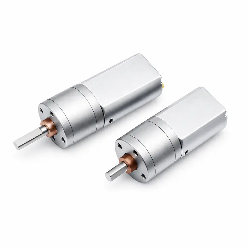
The KC-GM20-180SH combines a brushed 180 motor with the GM20 metal spur gearbox for applications that require reduced output speed and increased usable torque. This 180 dc gear motor uses a 20 mm gearbox and a D-shaped output shaft, providing a practical mechanical interface for small actuators, locking mechanisms, positioning assemblies and other geared drive systems. Voltage, gear ratio and output speed can be selected according to the required operating point rather than treating one motor specification as suitable for every load.
Engineering Configuration
The GM20 180 motor platform supports a 3 V–24 V DC supply range at the series level, while the listed geared configurations include 6 V and 12 V versions with output speeds from 10–1 000 rpm. The gearbox uses metal or powder-metallurgy gearing and supports round, D-cut and custom shafts. For engineers comparing an FK 180SH or FK 180SH motor reference, the core motor data should be checked by voltage, winding, no-load speed, efficiency point and stall characteristics before selecting a replacement. The gearbox ratio then determines the final speed and torque available at the output shaft.
180 Motor Mechanical And Gearbox Specifications
| Parameter | Specification |
|---|---|
| Product Configuration | |
| Brand | Kechen Motor (KC) |
| Model | KC-GM20-180SH |
| Product Name | GM20-180SH micro DC gear motor |
| Motor Type | Brushed DC gear motor |
| Gearbox Series | GM20 |
| Gearbox Type | Metal spur gearbox |
| Shaft Type | D-shaped shaft |
| Rated Voltage Range | 3 V–24 V DC |
| Speed And Torque | Customizable by winding and gear ratio |
| Mechanical Dimensions | |
| Gearbox Diameter | Ø20.0 mm |
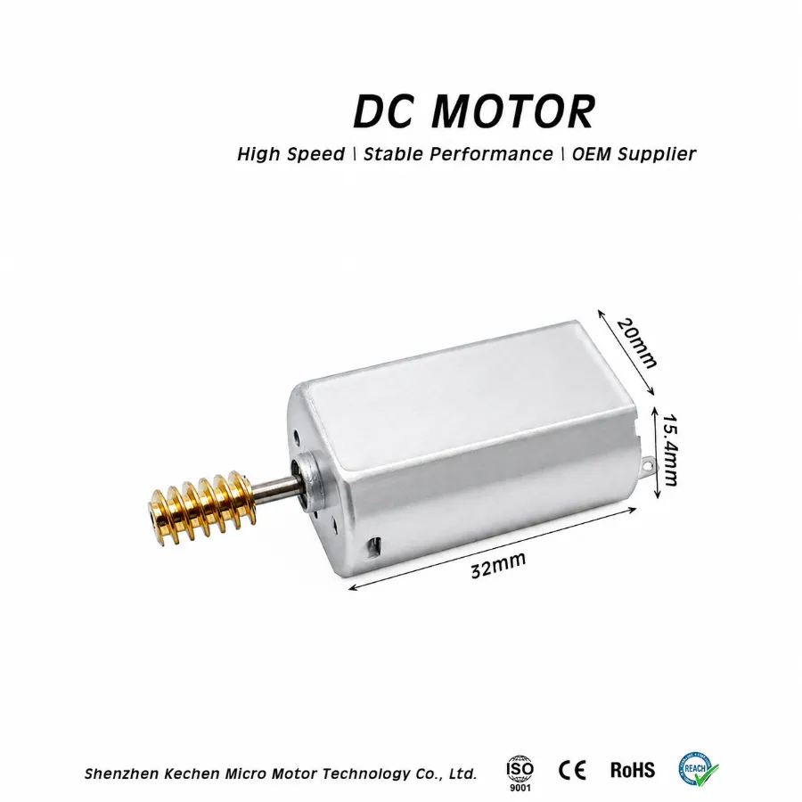
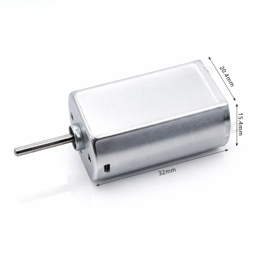
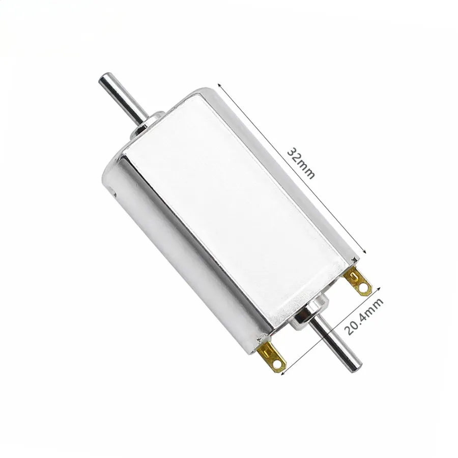
| Motor Body Length | 32.0 mm |
| Output Shaft Diameter | Ø4.0 mm |
| Output Shaft Type | D-shaped shaft |
| Shaft Length Options | 10.0 mm / 15.0 mm |
| Mounting | 2 × M2.5 screw holes |
| Mounting Hole Spacing | 15 mm |
| Weight | 55–65 g |
| Shown Dimension Configuration | |
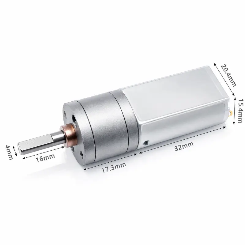
| Gearbox Length | 17.3 mm |
| Motor Body Length | 32 mm |
| Motor Body Width | 20.4 mm |
| Motor Body Height | 15.4 mm |
| Output Shaft Diameter | 4 mm |
| Output Shaft Length | 16 mm |
| Output Shaft | D-shaped shaft |
| GM20 Gearbox Data | |
| Product Name | GM20 gearbox |
| Gearbox Diameter | 20 mm |
| Gear Material | Powder metallurgy / metal gear |
| Shaft Options | Round shaft / D-cut shaft / custom shaft |
| Standard Ratio Options | 29:1 / 31:1 / 56:1 / 60:1 / 73:1 / 78:1 / 115:1 / 140:1 / 168:1 / 289:1 / 349:1 / 456:1 / 488:1 |
| Gear Ratio | Customizable |
| Typical Motor Match | KC-GM20-130 DC gear motor / KC-GM20-180 DC gear motor |
180 DC Motor Electrical Performance And Gear Ratio Data
| Configuration | Parameter | Value |
|---|---|---|
| Geared Motor Electrical Performance | ||
| 6 V Version | Rated Voltage | 6.0 V DC |
| No-load Current | ≤ 120 mA | |
| Output Speed | 10–1 000 rpm | |
| Rated Torque | 0.8–3.0 kg·cm | |
| Stall Torque | 3.5 kg·cm | |
| 12 V Version | Rated Voltage | 12.0 V DC |
| No-load Current | ≤ 80 mA | |
| Output Speed | 10–1 000 rpm | |
| Rated Torque | 1.0–4.0 kg·cm | |
| Stall Torque | 6.0 kg·cm | |
| Representative Gear Ratio And Output Data | ||
| 1:380 | No-load Output Speed / Rated Torque | 15 rpm / 4.0 kg·cm |
| 1:150 | No-load Output Speed / Rated Torque | 40 rpm / 2.2 kg·cm |
| 1:100 | No-load Output Speed / Rated Torque | 65 rpm / 1.5 kg·cm |
| 1:50 | No-load Output Speed / Rated Torque | 130 rpm / 0.8 kg·cm |
| 1:20 | No-load Output Speed / Rated Torque | 350 rpm / 0.4 kg·cm |
| 180 Motor Core Data | ||
| KC-180SH-2375 | Voltage | 3.0 V DC |
| No-load Speed | 6 100 rpm | |
| No-load Current | 106 mA | |
| Speed At Maximum Efficiency | 4 750 rpm | |
| Torque At Maximum Efficiency | 20 g·cm | |
| Current At Maximum Efficiency | 569 mA | |
| Output Power / Stall Torque | 1.7 W / 90.4 g·cm | |
| Stall Current | 2.1 A | |
| KC-180SH-18125 | Voltage | 12.0 V DC |
| No-load Speed | 15 000 rpm | |
| No-load Current | 158 mA | |
| Speed At Maximum Efficiency | 13 400 rpm | |
| Torque At Maximum Efficiency | 20 g·cm | |
| Current At Maximum Efficiency | 442 mA | |
| Output Power / Stall Torque | 5.3 W / 168.8 g·cm | |
| Stall Current | 4.1 A | |
| KC-180SH-13230 | Voltage | 24.0 V DC |
| No-load Speed | 15 000 rpm | |
| No-load Current | 95 mA | |
| Speed At Maximum Efficiency | 14 000 rpm | |
| Torque At Maximum Efficiency | 20 g·cm | |
| Current At Maximum Efficiency | 236 mA | |
| Output Power / Stall Torque | 5.7 W / 270 g·cm | |
| Stall Current | 1.8 A | |
| Performance Curve References | ||
| KC-180SH-18125 | Performance Curve Voltage | 12 V |
| KC-180SH-13230 | Performance Curve Voltage | 24 V |
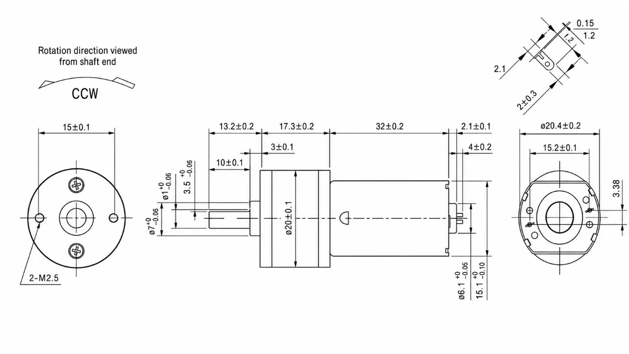
KC-GM20-180SH D-Shaped Shaft Dimensions
Performance Advantages
- The metal spur gearbox provides multiple reduction ratios for balancing output speed and torque according to the driven load.
- The 4 mm D-shaped shaft provides a defined flat surface for coupling, hub or gear engagement and helps reduce rotational slip at the connection.
- The 20 mm gearbox format supports integration where the drive envelope must remain controlled while retaining a geared output stage.
- Available 6 V and 12 V geared versions cover output speeds from 10–1 000 rpm, while the broader 180 brushed motor family includes 3 V, 12 V and 24 V winding references.
- Custom gear ratios, shaft configurations and motor windings allow the 180 metal gear motor to be matched to different speed, torque and installation requirements.
- Separate core-motor and gearbox data allow engineers to evaluate winding performance independently from the mechanical reduction stage before confirming a production configuration.
Selecting A Suitable 180 DC Gear Motor
Selection should begin with the required output rpm and continuous load torque. A higher reduction ratio lowers shaft speed and increases available geared torque, while a lower ratio retains more output speed. Supply voltage should then be matched to the control system and selected 180 brushed motor winding. Stall torque is useful for understanding the upper mechanical limit but should not be treated as a continuous operating point. For a 6 V 180 dc gear motor or 12 V 180 dc gear motor, current, duty cycle, gearbox loading and expected operating temperature should be reviewed together. Shaft length, D-flat geometry and mounting-hole spacing should also be verified against the final assembly drawing before production.