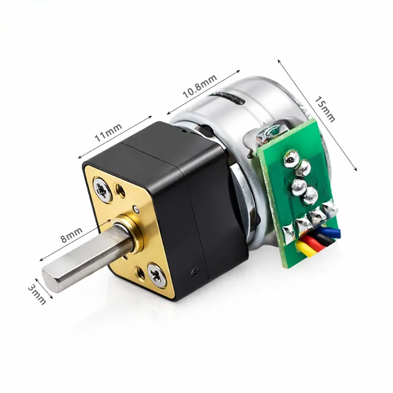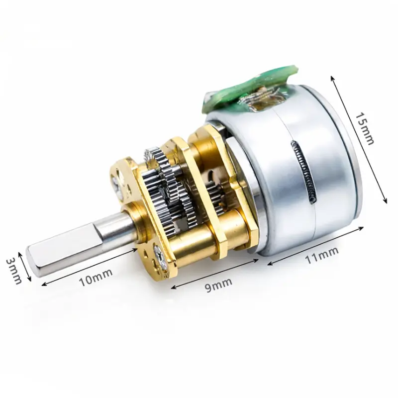
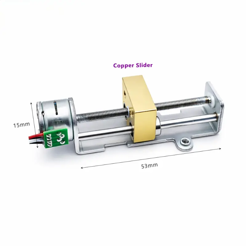
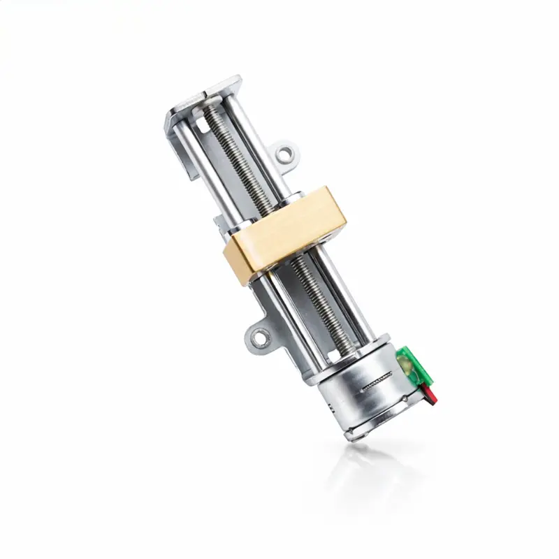
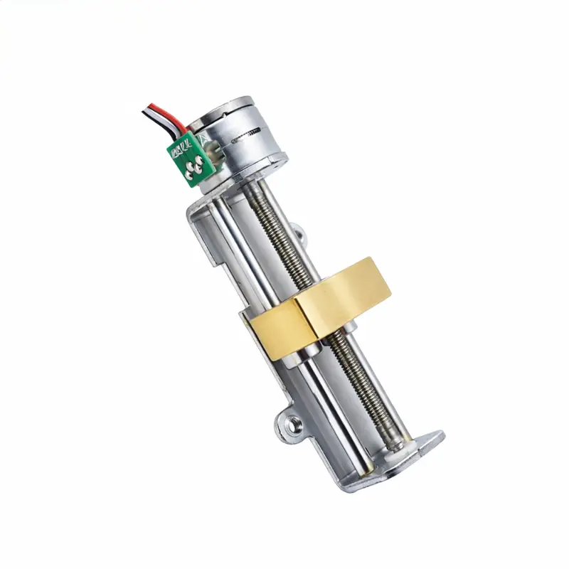
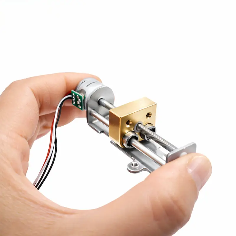
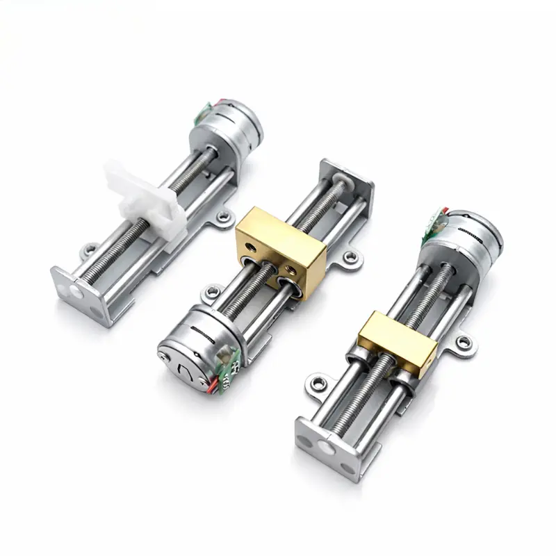
Motorized Linear Slide KC-15BY53 with 15mm 5V Stepper Motor & Copper Slider
KC-15BY53 Motorized Linear Slide Technical Specifications
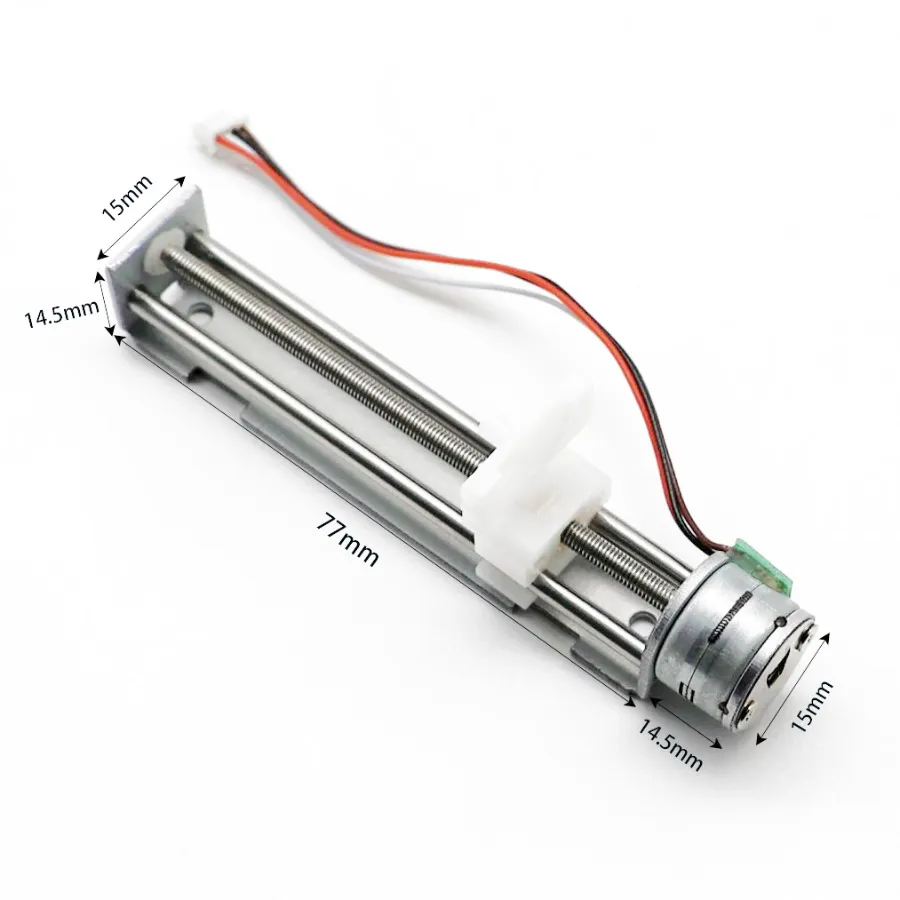
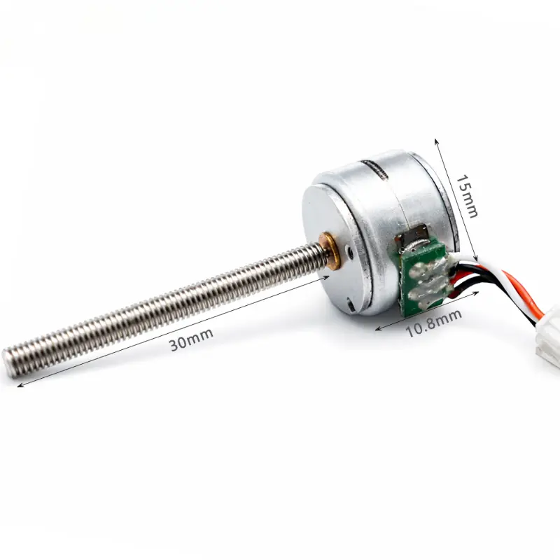
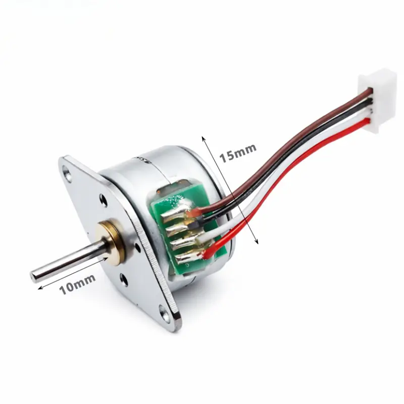
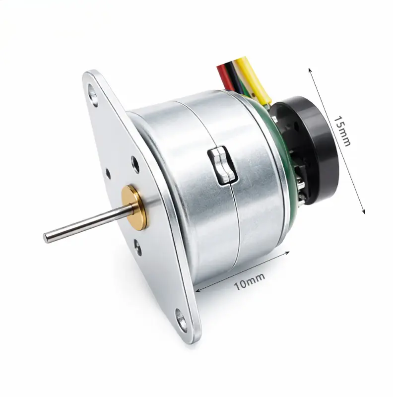
The KC-15BY53 motorized linear slide from Kechen Motor combines a 15 mm permanent magnet stepper motor, threaded lead screw, metal guide structure and copper slider in a 53 mm slide assembly. The integrated stepper motor linear stage converts controlled motor rotation into guided linear movement for small positioning mechanisms and OEM equipment.
Electrical & Performance Specifications
| Parameter | Specification |
|---|---|
| Rated Voltage | 5 V DC |
| Coil Resistance | 10 Ω ± 10% per phase (25 °C) |
| Number of Phases | 2 phases |
| Step Angle | 18 ° per step |
| Excitation Method | 2-2 phase excitation |
| Drive Mode | Bipolar drive |
| Pull-out Thrust | More than 400 gf at 800 PPS / 5 V |
| Insulation Class | Class E (coils) |
| Insulation Resistance | 100 MΩ at 500 V DC |
| Operating Temperature Range | 0 °C to +55 °C |
Performance Note: Pull-out thrust is specified under the stated test conditions and should not be interpreted as a continuous rated axial load. Usable thrust and positioning performance depend on drive conditions, lead screw characteristics and the connected mechanical load.
Mechanical & Connection Specifications
| Parameter | Specification |
|---|---|
| Product Configuration | |
| Product Model | KC-15BY53 |
| Brand | Kechen Motor |
| Product Type | Linear stepper motor with lead screw and copper slider |
| Motor Type | Permanent magnet stepper motor |
| Actuator Structure | Integrated linear slide assembly |
| Motion Mechanism | Threaded lead screw and copper slider |
| Guide Structure | Integrated metal guide rail and bracket |
| Slider Material | Copper |
| Copper Slider Reference | 10833 |
| Mechanical Dimensions | |
| Motor Diameter | 15 mm |
| Overall Assembly Length | 64 mm |
| Slide Assembly Length | 53 mm |
| Motor-end Mounting Height | 27 mm |
| Motor-end Hole Spacing | 15 mm |
| Slider Dimension (Top View) | 10 mm |
| Slider Dimension (Side View) | 7.3 mm |
| Mounting Holes | 2 × M2.5 |
| Additional Mounting Holes | 2 × Ø 3.2 mm |
| Mounting Boss Diameter | 2 × Ø 6 mm |
| Mounting Hole Position | 41.5 mm |
| Additional Mounting Dimension | 34.5 mm |
| Lead Screw Type | Threaded lead screw |
| Lead Screw Pitch | Not specified; requires confirmation |
| Usable Linear Stroke | Not specified; requires confirmation |
| Wiring & Pin Configuration | |
| Connector Type | 1.25 mm pitch, 4-pin (1.25-4P) |
| Wire Specification | UL1571, 30 AWG |
| Lead Wire Length | 90 ± 10 mm |
| Connection Type | 4-wire bipolar |
| Pin 1 | Brown — phase A− |
| Pin 2 | Black — phase A+ |
| Pin 3 | White — phase B− |
| Pin 4 | Red — phase B+ |
| Engineering Drawing Information | |
| Drawing Number | 01.03.15BY53003 |
| Drawing Revision | A0 |
| Drawing Date | 2026-03-03 |
| Drawing Type | Finished motor assembly drawing |
| Drawing Scale | 1:1 |
| RoHS Requirement | Specified in engineering drawing |
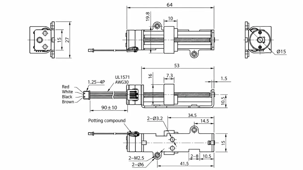
Dimensional Note: All mechanical dimensions are in millimeters unless otherwise specified. The 53 mm value refers to the slide assembly length, not the usable linear stroke. Lead screw pitch and effective travel require confirmation before final motion calculations.
KC-15BY53 Motorized Linear Slide Dimensions
The engineering drawing identifies the motor mounting interface, guide assembly, copper slider and lead screw arrangement. Review the mounting-hole positions and available installation space when integrating this linear actuator slide into a larger mechanism.
Engineering Advantages of the KC-15BY53
Integrated Linear Motion
The lead screw and guided copper slider provide a mechanical path for converting stepper motor rotation into linear displacement without a separate slide mechanism.
Stepper-Controlled Positioning
Bipolar stepper operation supports pulse-controlled movement. Actual displacement per step depends on the lead screw pitch and drive configuration.
Defined Mounting Interface
The metal bracket, documented mounting features and wired connector interface support mechanical layout and electrical integration during OEM development.
OEM Configuration Review
For projects requiring different travel distances, mounting arrangements, lead screw specifications or electrical connections, Kechen Motor can review the requested configuration against mechanical drawings and application requirements. Feasibility and final performance are subject to engineering confirmation and sample validation.
Payment & Shipping Information
Payment
- Payment Terms:
Payment arrangements are confirmed during quotation and commercial review. - Order Documentation:
The approved quotation and proforma invoice specify the agreed commercial conditions.
Shipping
- Shipping Method:
Transport options are reviewed according to destination, order quantity and project requirements. - Production & Dispatch:
Manufacturing and dispatch schedules are confirmed based on the approved product configuration and order conditions. - Export Packaging:
Packaging requirements can be reviewed according to the selected shipment method and product protection needs.
Frequently Asked Questions
Q1. Does the KC-15BY53 Provide 53 mm of Linear Travel?
No confirmed 53 mm stroke is specified. The dimension refers to the slide assembly length. The usable travel must be verified from the mechanical configuration before selection.
Q2. What Driver Is Required for This Motorized Linear Slide?
The KC-15BY53 uses a two-phase, four-wire bipolar stepper motor. A compatible bipolar stepper driver is required, with its electrical settings selected according to the motor winding specifications and the intended operating conditions.
Q3. How Is the Linear Displacement Per Step Calculated?
Linear displacement depends on the lead screw lead and the commanded motor rotation. For an ideal single-start screw without missed steps, full-step displacement equals screw lead divided by the number of full steps per revolution. The screw pitch and lead must be confirmed before calculating displacement for this model.
Q4. Can the Specified Pull-out Thrust Be Used as the Continuous Working Load?
Not directly. Pull-out thrust is a performance result under defined test conditions. Continuous working load should be evaluated against travel speed, acceleration, duty cycle, temperature and the mechanical load on the slider.
Q5. Does the Assembly Include Limit Switches or Position Feedback?
The supplied specifications do not identify integrated limit switches, encoders or position sensors. Any requirement for end-position detection or feedback should be confirmed during the technical review.
Q6. What Information Is Needed for an OEM Configuration Request?
Provide the required stroke, axial load, travel speed, operating duty cycle, available installation dimensions, supply voltage, mounting requirements and estimated order quantity. These details allow Kechen Motor to assess the existing configuration or proposed modifications.
Technical Specification Notice
Specifications are for reference only. Final parameters should be confirmed based on approved samples and project requirements. Lead screw pitch, usable linear stroke and application-specific load performance require confirmation before production approval.
Related Motor Specifications
motorized linear slide | stepper motor linear stage | linear actuator slide | stepper motor linear actuator | stepper linear actuator | 5 V linear actuator | micro linear stepper motor | motorized lead screw actuator | miniature linear stepper motor | 15 mm permanent magnet stepper motor | 53 mm linear slide assembly | copper slider lead screw actuator | 4-wire bipolar stepper motor | KC-15BY53