15mm Geared Stepper Motor with D-Shaft, Gear Ratios and Encoder Options
KC-GM12-15BY 15mm Geared Stepper Motor With D-Cut Shaft
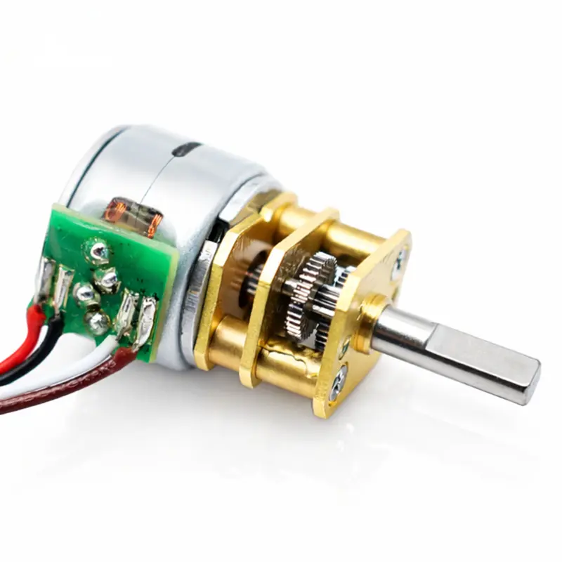
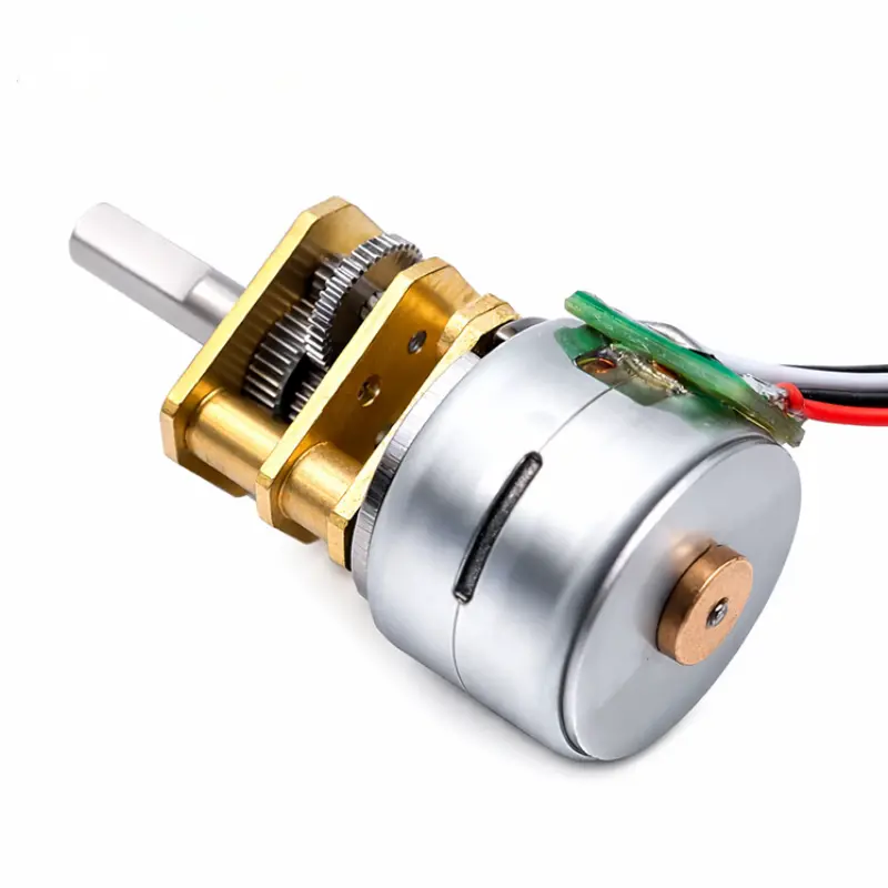
KC-GM12-15BY is a 15 mm, 2-phase permanent magnet geared stepper motor designed for controlled low-speed motion where a small motor diameter, gear reduction and configurable output shaft are required. The platform supports multiple winding voltages, steel gearing, D-cut or threaded shafts and optional encoder configurations for OEM motion-control integration.
Product Configuration Overview
15mm Geared Stepper Motor Specifications
Electrical, mechanical and configuration data for the KC-GM12-15BY geared PM stepper motor platform.
| Parameter | Specification | Engineering Detail |
|---|---|---|
| Primary Model | KC-GM12-15BY | 15 mm geared stepper motor platform |
| Motor Type | 2-phase geared PM stepper motor | Permanent magnet stepping construction |
| Rated Voltage Options | 3 V, 5 V, 6 V, 9 V, 12 V, 24 V | Selected according to winding configuration |
| Rated Torque | Maximum 3 kgf·cm | Configuration-dependent output |
| Motor Step Angle | 18°/step | Step angle before gearbox reduction |
| General Reduction Ratios | 3:1, 10:1, 50:1, 99:1, 145:1, 196:1, 230:1, 238:1, 378:1, 500:1, 760:1, 1000:1, 1200:1 | General product configuration range |
| Phase Resistance | 10–40 Ω/phase | Depends on winding version |
| Phase Current | 210–500 mA/phase | Winding-dependent |
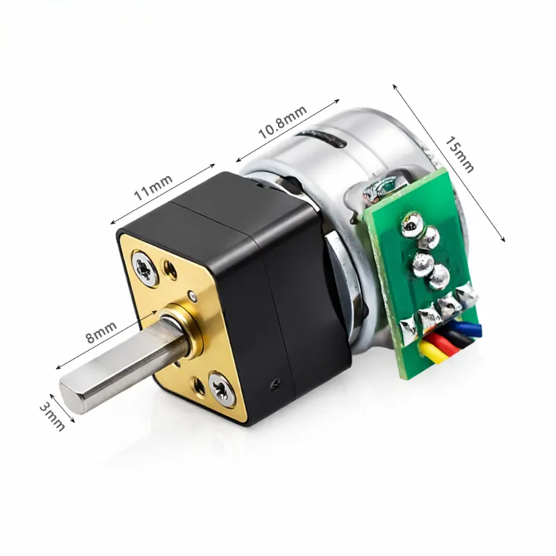
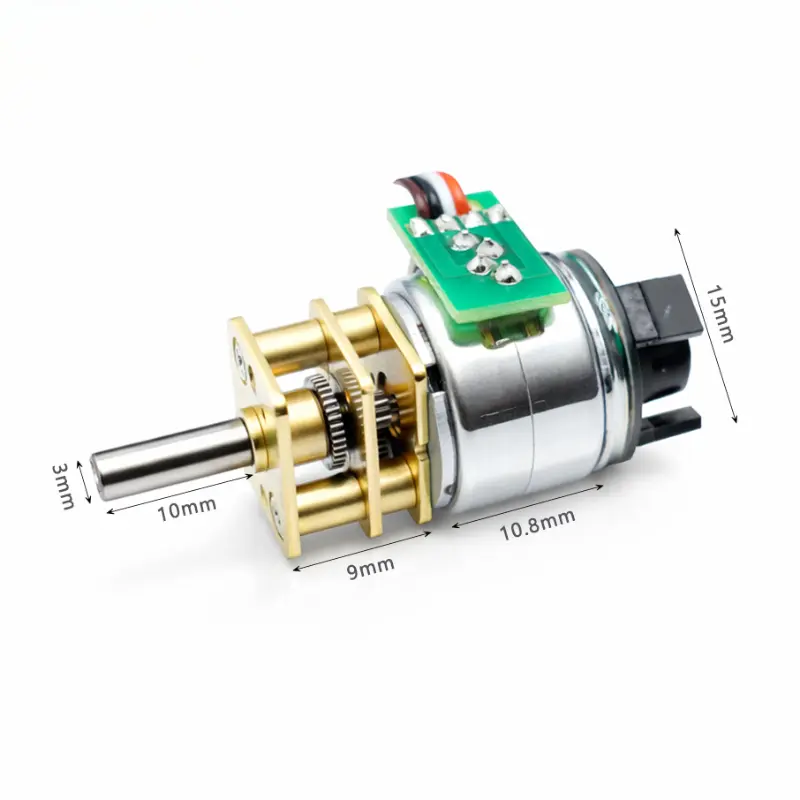
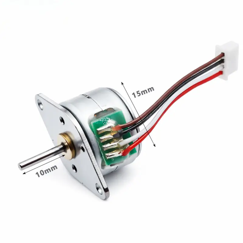
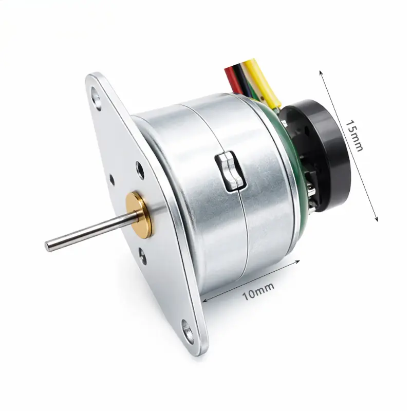
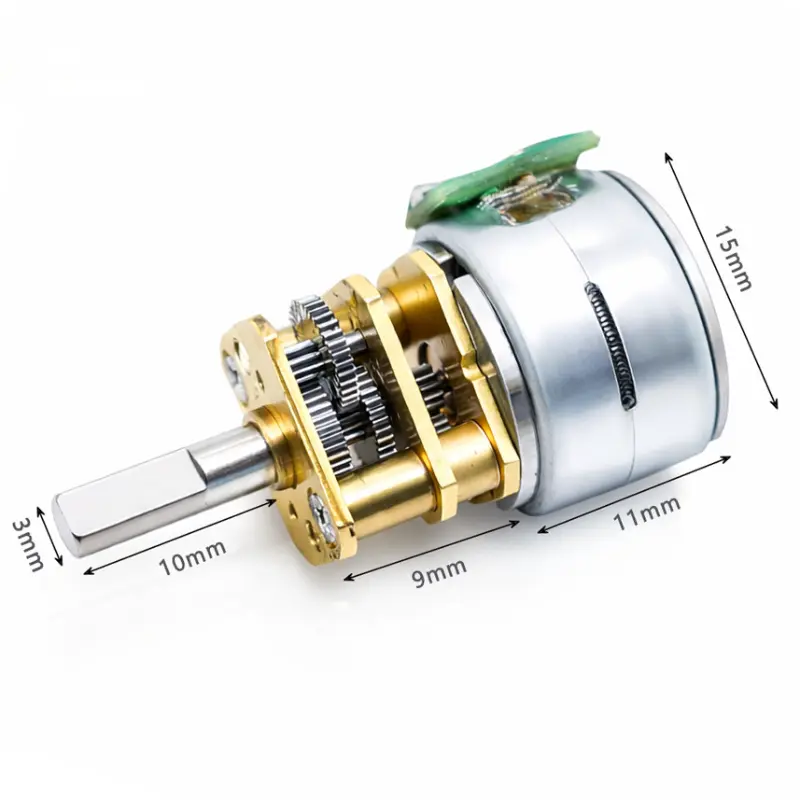
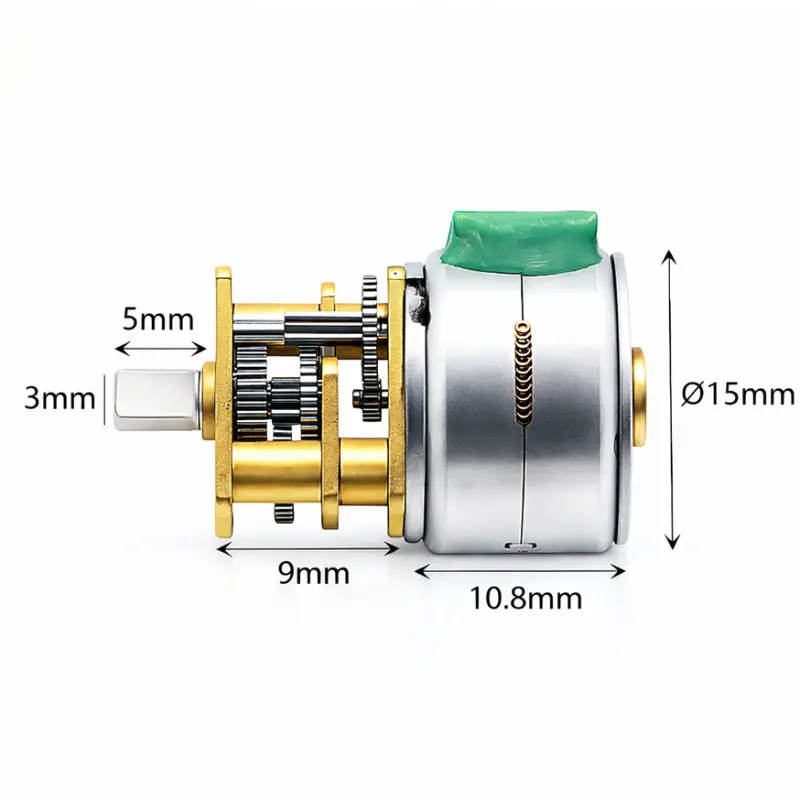
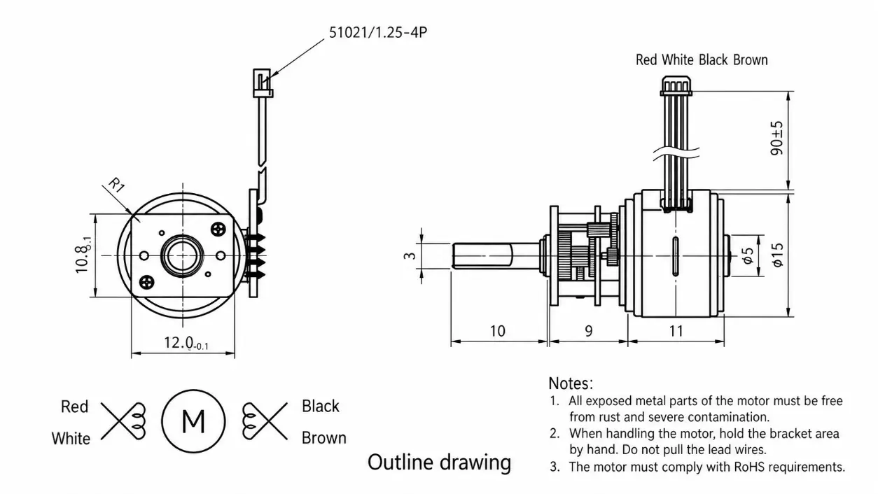
| Motor Diameter | 15 mm | Main motor body diameter |
| Motor Body Length | 11 mm | D-cut shaft version |
| Gearbox Length | 9 mm | D-cut shaft configuration |
| Output Shaft Length | 10 mm | Standard D-cut version |
| Output Shaft Diameter | 3 mm | Standard D-cut output |
| D-Cut Depth | 0.5 mm | Standard shaft flat |
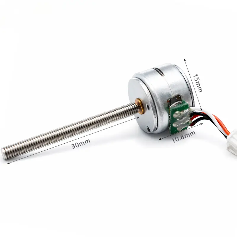
| Shaft Options | D-cut, M3, M4 or custom | Mechanical output can be adapted to the application |
| Shaft Diameter Options | 3 mm / 4 mm | Model-dependent |
| Shaft Length Options | 8–15 mm or custom-made | Custom shaft length is supported |
| Encoder Options | 3 PPR / 7 PPR / 12 PPR | Optional motion feedback configuration |
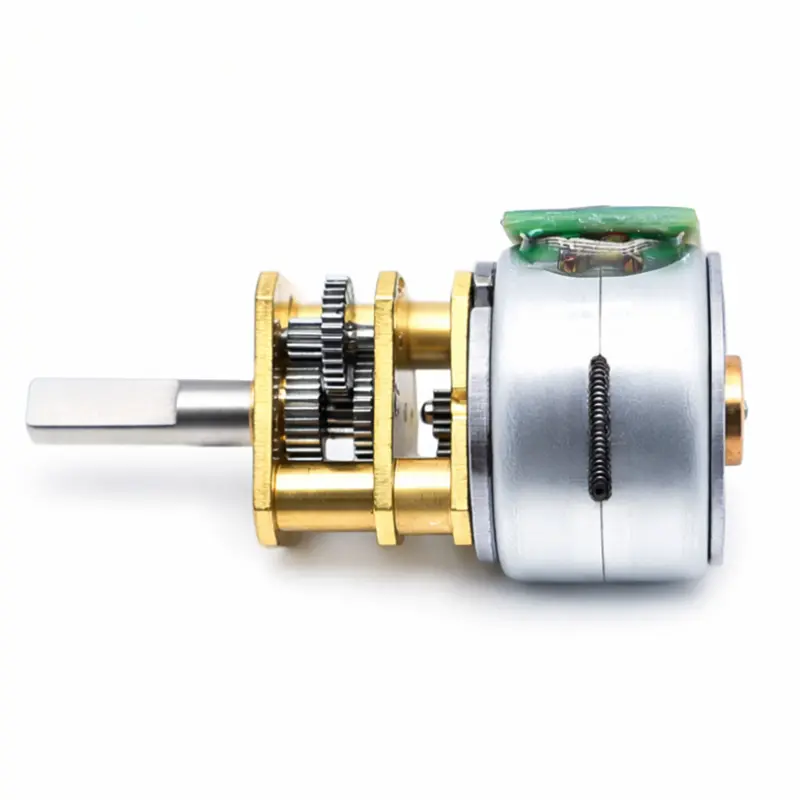
| Gear Material | Steel | Gearbox transmission material |
| Connector | 51021 / 1.25-4P | Standard D-shaft configuration |
| Terminal Options | 2-pin, 1.25 / 1.5 / 2.0 / 2.54 mm | Connector configuration can vary by project |
| Lead Wire Length | 90 ± 5 mm | Standard dimensional data |
| Lead Wire / Phase | Red: A; White: A̅; Black: B; Brown: B̅ | Four-wire phase reference |
| Operating Temperature | −10 °C to +55 °C typical | General specification range |
| Maximum Starting Frequency | 800–1200 pps | Configuration-dependent |
| Insulation Resistance | ≥ 50 MΩ at 300 V DC | Common motor technical data |
| Noise | ≤ 50 dB(A) | Common motor technical data |
| Weight | 17 g | General product data |
| Compliance | CE, RoHS | Product compliance data |
800 PPS Geared Stepper Motor Performance Data
Performance comparison for three winding configurations using the same 15 mm geared stepper motor platform and gearbox structure.
Test Configurations
8 gf·cm detent torque | 45 gf·cm holding torque
8 gf·cm detent torque | 40 gf·cm holding torque
8 gf·cm detent torque | 55 gf·cm holding torque
| Gear Ratio | Stage | Gearbox Length | Output Step Angle | Speed | J2510-N Torque | J2520-N Torque | J2540-N Torque |
|---|---|---|---|---|---|---|---|
| 10:1 | 2 | 9 mm | 1.80°/step | 240.0 rpm | 160 gf·cm | 96 gf·cm | 160 gf·cm |
| 20:1 | 3 | 9 mm | 0.90°/step | 120.0 rpm | 280 gf·cm | 168 gf·cm | 280 gf·cm |
| 30:1 | 3 | 9 mm | 0.60°/step | 80.0 rpm | 420 gf·cm | 252 gf·cm | 420 gf·cm |
| 50:1 | 4 | 9 mm | 0.36°/step | 48.0 rpm | 600 gf·cm | 360 gf·cm | 600 gf·cm |
| 75:1 | 4 | 9 mm | 0.24°/step | 32.0 rpm | 900 gf·cm | 540 gf·cm | 900 gf·cm |
| 100:1 | 4 | 9 mm | 0.18°/step | 24.0 rpm | 1200 gf·cm | 720 gf·cm | 1200 gf·cm |
| 165:1 | 5 | 9 mm | 0.11°/step | 14.5 rpm | 1650 gf·cm | 990 gf·cm | 1650 gf·cm |
| 210:1 | 5 | 9 mm | 0.09°/step | 11.4 rpm | 2100 gf·cm | 1260 gf·cm | 2100 gf·cm |
| 250:1 | 5 | 9 mm | 0.07°/step | 9.6 rpm | 2500 gf·cm | 1500 gf·cm | 2500 gf·cm |
| 298:1 | 5 | 9 mm | 0.06°/step | 8.1 rpm | 2980 gf·cm | 1788 gf·cm | 2980 gf·cm |
| 380:1 | 5 | 9 mm | 0.05°/step | 6.3 rpm | 3800 gf·cm | 2280 gf·cm | 3800 gf·cm |
KC-GM12-15BY D-Shaft Dimensions Drawing
Mechanical reference for the 15 mm motor body, 9 mm gearbox and 3 mm D-cut output shaft configuration.
Performance Advantages
- 15 mm motor diameter with a 9 mm gearbox supports integration where installation space is limited.
- Multiple reduction configurations allow engineers to balance output speed, output step angle and pull-out torque.
- Documented 800 pps gearbox data covers 10:1 to 380:1 ratios with output step angles from 1.80°/step to 0.05°/step.
- Available 3 V to 24 V winding options support different control-system voltage requirements.
- D-cut, M3, M4 and custom shaft configurations provide different mechanical coupling options.
- Optional 3 PPR, 7 PPR and 12 PPR encoder configurations support applications requiring motion feedback.
- Steel gearing and configurable electrical parameters allow OEM adaptation for defined speed, torque and installation requirements.
Available Configurations And Customization
Model Configuration
The KC-GM12-15BY platform includes D-cut shaft, threaded shaft and encoder-compatible configurations. Documented winding variants include J2510-N, J2520-N and J2540-N for different resistance, current and voltage requirements.
OEM Configuration Options
Shaft length and motor electrical parameters can be configured according to project requirements. Available voltage references include 3 V, 5 V, 6 V, 9 V, 12 V and 24 V. Shaft configurations include D-cut, M3, M4 and custom designs, while encoder options include 3 PPR, 7 PPR and 12 PPR.
Payment And Shipping
Payment
- Configuration Confirmation:
Motor voltage, reduction ratio, shaft configuration, connector and encoder requirements should be confirmed before quotation. - Payment Terms:
Applicable payment terms are confirmed in the formal quotation according to the order and project requirements.
Shipping
- Shipping Method:
The shipping method is selected according to destination, shipment size and project requirements. - Dispatch Arrangement:
Packing and shipment details are confirmed with the buyer before dispatch.
KC-GM12-15BY FAQ
What Voltage Options Are Available For The KC-GM12-15BY?
The general product specification lists 3 V, 5 V, 6 V, 9 V, 12 V and 24 V winding options. Documented performance variants include 5 V and 12 V configurations.
Can The Geared Stepper Motor Be Supplied With An Encoder?
Yes. The available encoder references are 3 PPR, 7 PPR and 12 PPR, allowing the motor configuration to be matched to applications that require motion feedback.
What Shaft Configurations Are Available?
The product data lists a 3 mm D-cut shaft, M3 and M4 threaded options, plus custom shaft designs. Shaft diameter references include 3 mm and 4 mm, and shaft length can also be customized.
Which Gear Ratios Have Detailed 800 PPS Performance Data?
Detailed 800 pps test data is provided for 10:1, 20:1, 30:1, 50:1, 75:1, 100:1, 165:1, 210:1, 250:1, 298:1 and 380:1 ratios. Additional ratios are available within the general product configuration range.
How Does The Gear Ratio Affect Output Motion?
Within the documented test data, increasing the reduction ratio reduces output speed and output step angle while increasing available pull-out torque according to the selected winding and gearbox configuration.
Can The Electrical Parameters Be Customized?
Yes. Motor electrical parameters and shaft length can be configured according to customer requirements. Final configuration should be confirmed against the required voltage, current, torque, speed and mechanical interface.