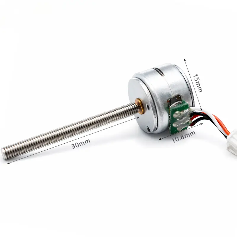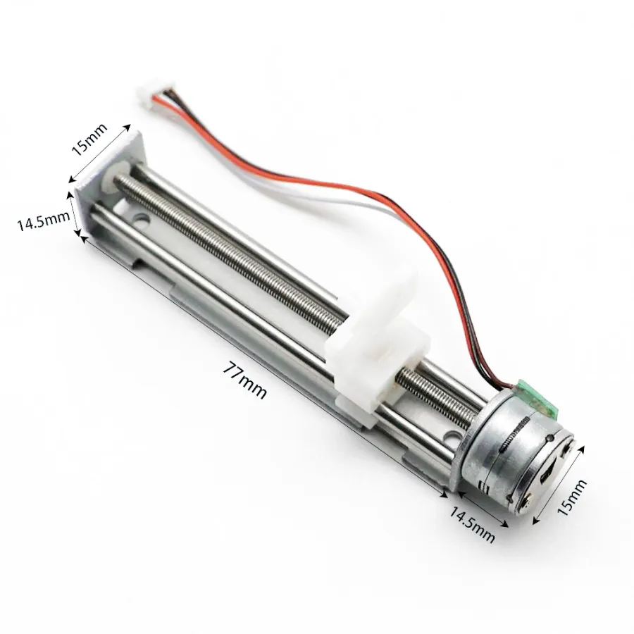
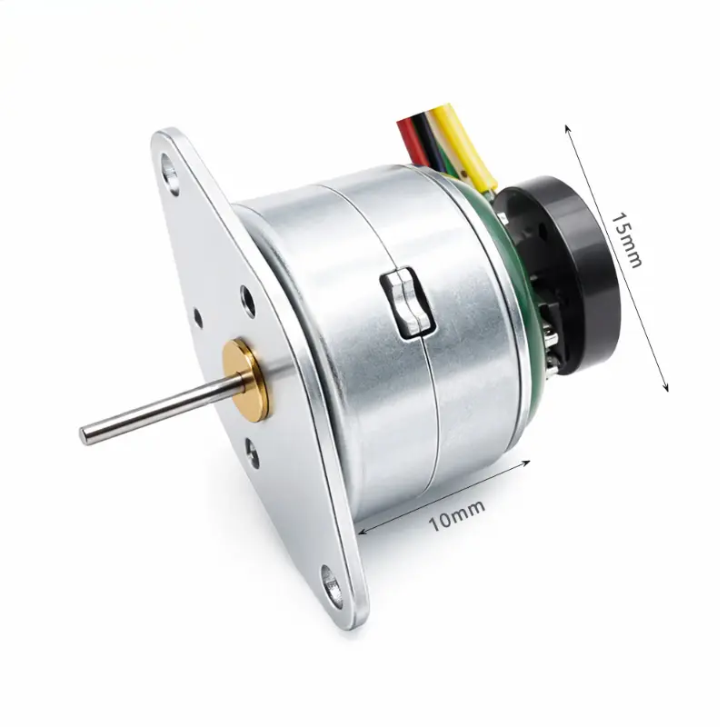
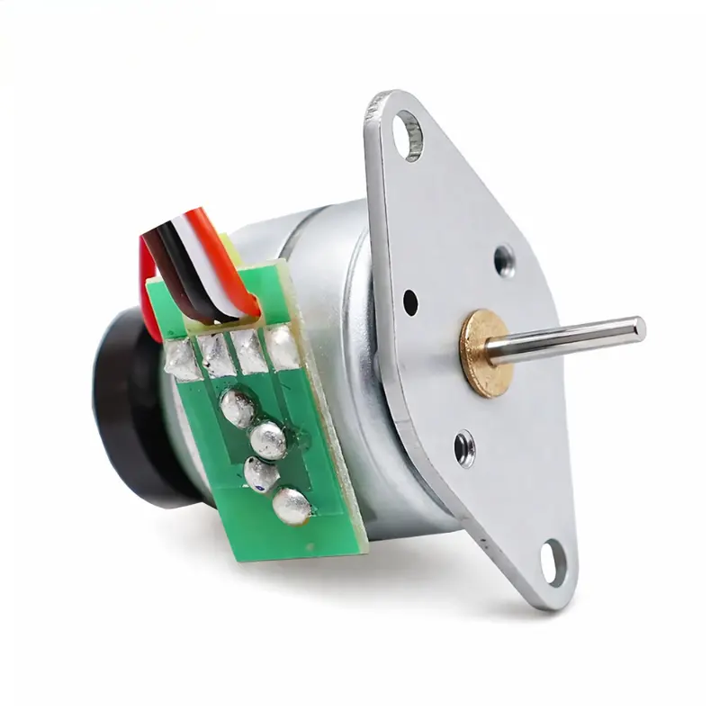
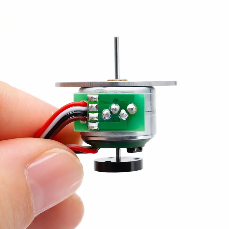
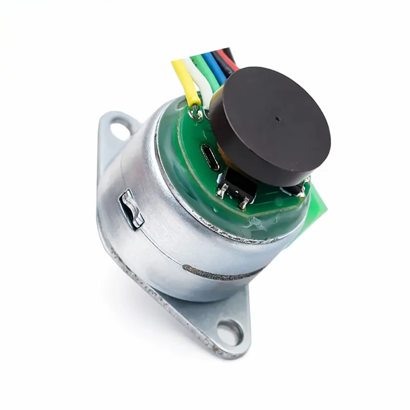
Small Stepper Motor with Encoder, 15mm Permanent Magnet, 5V and 12V
15mm Micro Stepper Motor With Encoder Technical Data
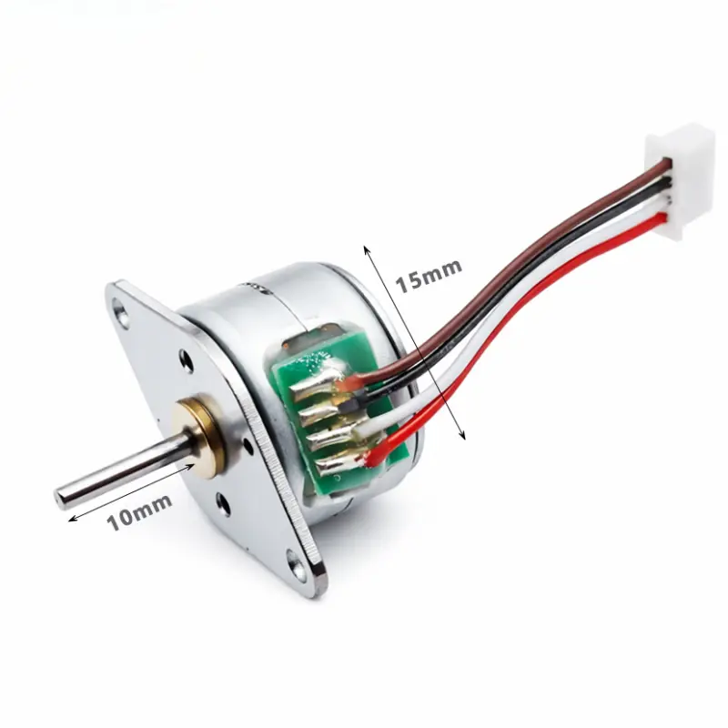
The KC-15BY25 series is a Ø15 mm permanent magnet micro stepper motor designed for positioning mechanisms where motor diameter, step control and encoder integration must be considered together. This small stepper motor with encoder is available with 5 V and 12 V winding configurations, while the mechanical platform retains the same 18° step angle and 15 mm motor housing diameter.
Electrical Performance By Model
Electrical characteristics for the available KC-15BY25 winding configurations. Test reference: 800 PPS.
| Model | Voltage | Resistance | Current | Detent Torque | Holding Torque | Step Angle | Excitation Mode |
|---|---|---|---|---|---|---|---|
| KC-15BY2510-N1 | 5 V DC | 10 Ω/phase | 400 mA/phase | 8 gf·cm | 45 gf·cm | 18° | 2-2 phase |
| KC-15BY2520-N1 | 5 V DC | 20 Ω/phase | 210 mA/phase | 8 gf·cm | 40 gf·cm | 18° | 2-2 phase |
| KC-15BY2540-N1 | 12 V DC | 40 Ω/phase | 300 mA/phase | 8 gf·cm | 55 gf·cm | 18° | 2-2 phase |
Motor, Mechanical And Wiring Specifications
Common construction, dimensional and connection data for the KC-15BY25 permanent magnet stepper motor with encoder.
| Parameter | Specification | Parameter | Specification |
|---|---|---|---|
| General Motor Data | |||
| Product Type | Permanent magnet stepper motor with encoder | Brand | Kechen Motor |
| Product Family | KC-15BY25 | Header Model | KC-15BY2540 |
| Motor Diameter | Ø15 mm | Motor Thickness | 17.2 mm |
| Step Angle | 18° | Excitation Mode | 2-2 phase |
| Test Condition | 800 PPS | Encoder | Yes |
| Insulation Resistance | ≥ 50 MΩ at 300 V DC | Noise | ≤ 50 dB(A) |
| Working Temperature | 10–50 °C | Housing Diameter | Ø15 mm |
| Mechanical Dimensions | |||
| Flange Overall Width | 20 ± 0.2 mm | Flange Reference Height | (15.7) mm |
| Motor Body Length | 10.7 mm | Shaft Protrusion | 7.5 ± 0.5 mm |
| Motor-To-Shaft-End Length | 18.2 mm | Overall Axial Length | 24.3 mm |
| Flange Plate Thickness | 0.5 mm | Output Shaft Diameter | Ø1.5 mm, tolerance +0 / −0.05 mm |
| D-Flat Height | 1.14 mm, tolerance +0.05 / 0 mm | D-Flat Length | 4.9 ± 0.05 mm |
| Front Center Feature | Ø1 mm, tolerance +0.03 / 0 mm | Front Reference Diameter | Ø11.5 ± 0.05 mm |
| Second Reference Diameter | Ø9.4 ± 0.05 mm | Threaded Holes | 2 × M1.4 |
| Mounting Holes | 2 × Ø2.1 ± 0.1 mm | Mounting Ear Radius | 2 × R2 |
| Angular References | 36° and 45° | Rotation Reference | CW / CCW viewed from flange side |
| Motor Connection | |||
| Motor Connection | 2-2 phase | Motor Connector | MOLEX 1.25 × 4P |
| Motor Lead Wire | UL1571 AWG 30 | Motor Lead Length | 300 ± 10 mm |
| Motor Wire Colors | Brown, black, white, red | Pin 1 | Red — Phase A |
| Pin 2 | White — Phase A̅ | Pin 3 | Black — Phase B |
| Pin 4 | Brown — Phase B̅ | Motor Phase Wiring | Red A, white A̅, black B, brown B̅ |
| Encoder Connection | |||
| Encoder Connector | MOLEX 1.25 × 6P | Encoder Lead Wire | UL1571 AWG 30 |
| Encoder Lead Length | 300 ± 10 mm | Encoder Pins 1–3 | Pin 1 red, Pin 2 black, Pin 3 blue |
| Encoder Pins 4–6 | Pin 4 green, Pin 5 white, Pin 6 yellow | Encoder Signal Functions | Requires confirmation from the applicable encoder specification |
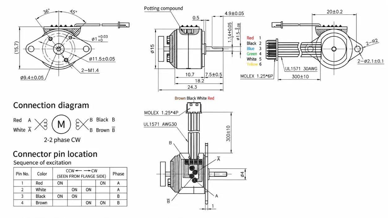
KC-15BY25 Outline Dimensions
Use the mechanical drawing when checking shaft position, mounting features, connector routing and available installation space.
Engineering Advantages
- 15 mm Motor Platform: The Ø15 mm housing supports integration where the motor envelope is a primary mechanical constraint.
- Encoder Configuration: The six-wire encoder connection provides an encoder-equipped motor platform, while final signal assignments should be confirmed for the selected encoder configuration.
- Multiple Winding Options: Available 5 V and 12 V configurations allow the winding to be selected around the intended driver and system power architecture.
- Defined Holding Torque: Available configurations provide 40–55 gf·cm holding torque, allowing comparison between winding options during motor selection.
- Mechanical Integration: The Ø1.5 mm D-flat shaft, mounting holes and reference diameters provide defined interfaces for coupling and mechanism design.
- Project Customization: Shaft length and motor parameters can be adjusted according to application requirements and confirmed through sample validation.
Payment And Order Confirmation
- Commercial Terms: Payment terms are confirmed in the formal quotation according to the approved motor configuration and order requirements.
- Configuration Confirmation: Voltage, winding, shaft dimensions, lead wires, connector and encoder requirements should be confirmed before production.
- Sample Validation: Final technical parameters should be based on approved samples and the requirements of the customer’s application.
Shipping Information
- Shipping Method: The suitable shipping method is confirmed according to destination, shipment size and project requirements.
- Freight Confirmation: Shipping cost is confirmed separately according to the destination and final packed shipment.
- Technical Documents: Motor model, approved configuration and applicable drawing should be checked against the purchase documentation before shipment.
KC-15BY25 FAQ
What Type Of Stepper Motor Is The KC-15BY25?
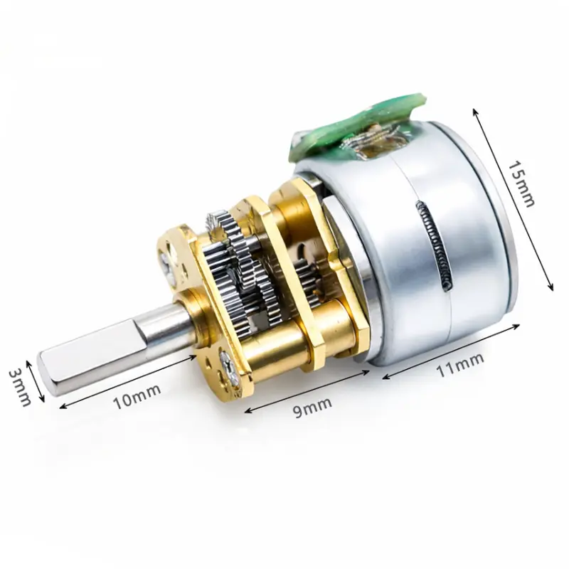
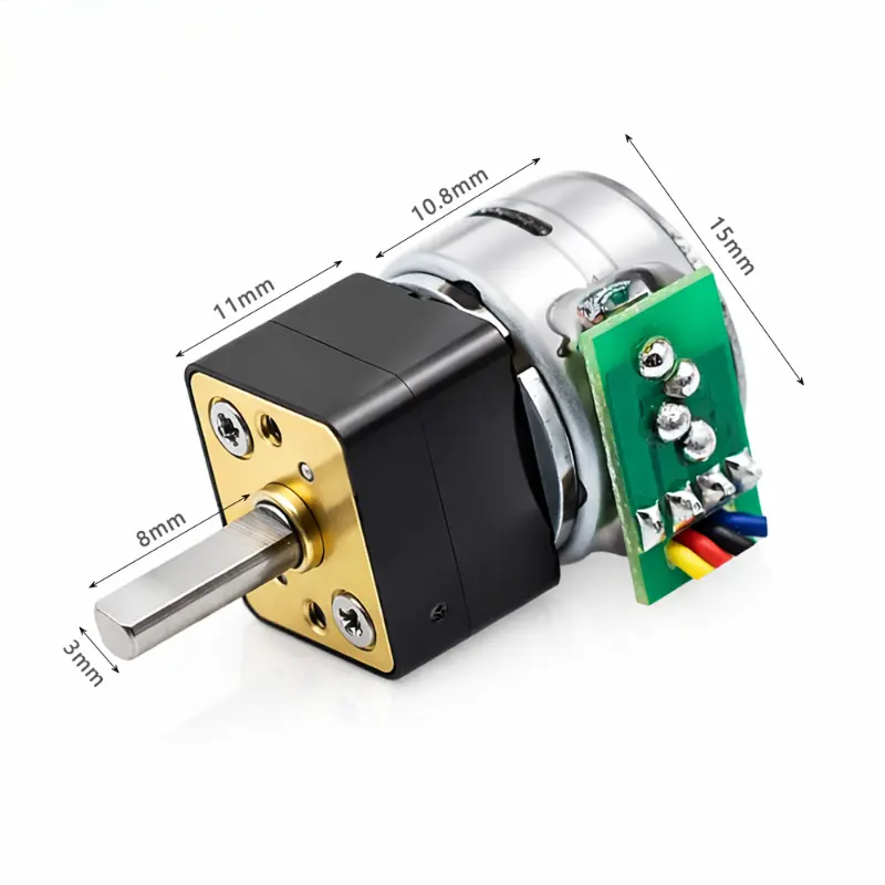
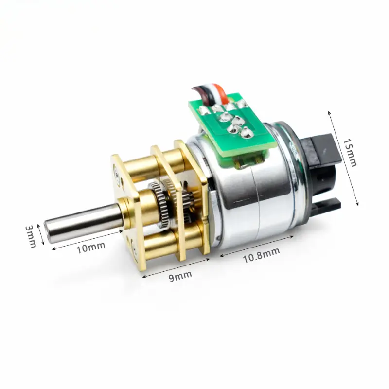
It is a Ø15 mm permanent magnet micro stepper motor with an encoder configuration. It is not a geared stepper motor and does not include a reduction gearbox.
Are Both 5 V And 12 V Versions Available?
Yes. KC-15BY2510-N1 and KC-15BY2520-N1 are specified at 5 V DC, while KC-15BY2540-N1 is specified at 12 V DC. Resistance, phase current and holding torque differ between these windings.
What Is The Step Angle?
The supplied models use an 18° step angle with 2-2 phase excitation. Driver selection and motion-control settings should be matched to the actual winding configuration.
What Are The Encoder Signal Assignments?
The supplied drawing identifies six encoder lead colors but does not define their corresponding signal functions. Encoder pin functions therefore require confirmation for the selected configuration.
Can The Shaft Length Be Customized?
Yes. Shaft length and motor parameters can be customized according to project requirements. Final dimensions and electrical characteristics should be confirmed through the approved sample.
Which Holding Torque Options Are Listed?
The supplied data lists 40 gf·cm, 45 gf·cm and 55 gf·cm holding torque depending on the selected winding model.
Specifications are for reference only. Final parameters should be confirmed based on approved samples and project requirements.