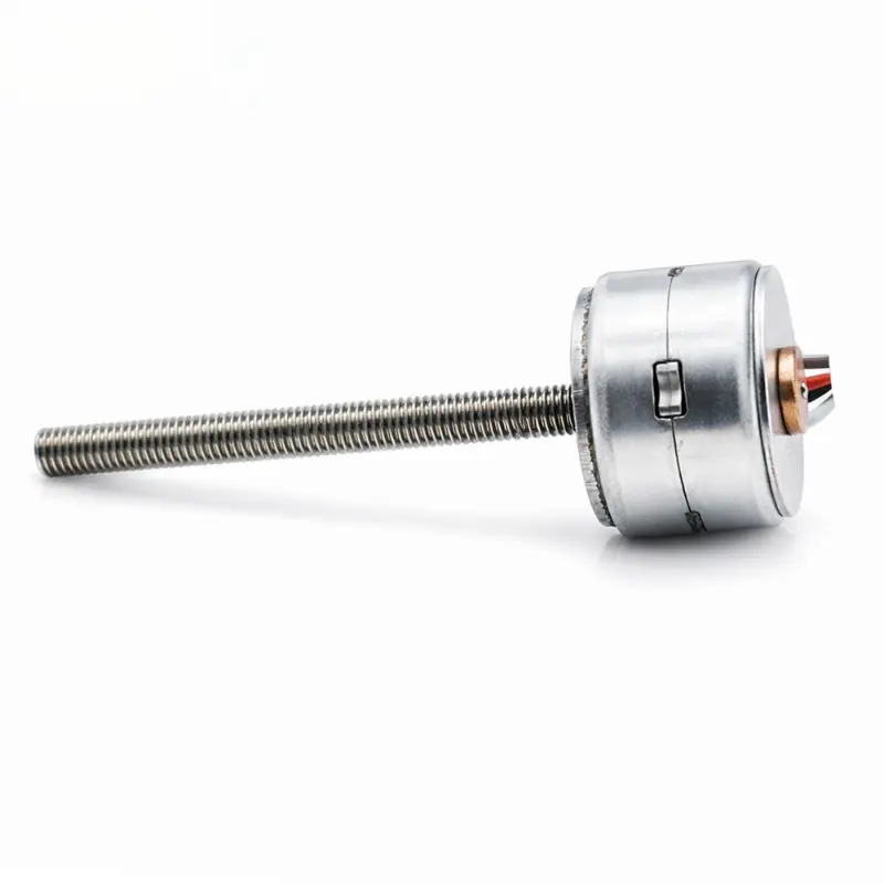
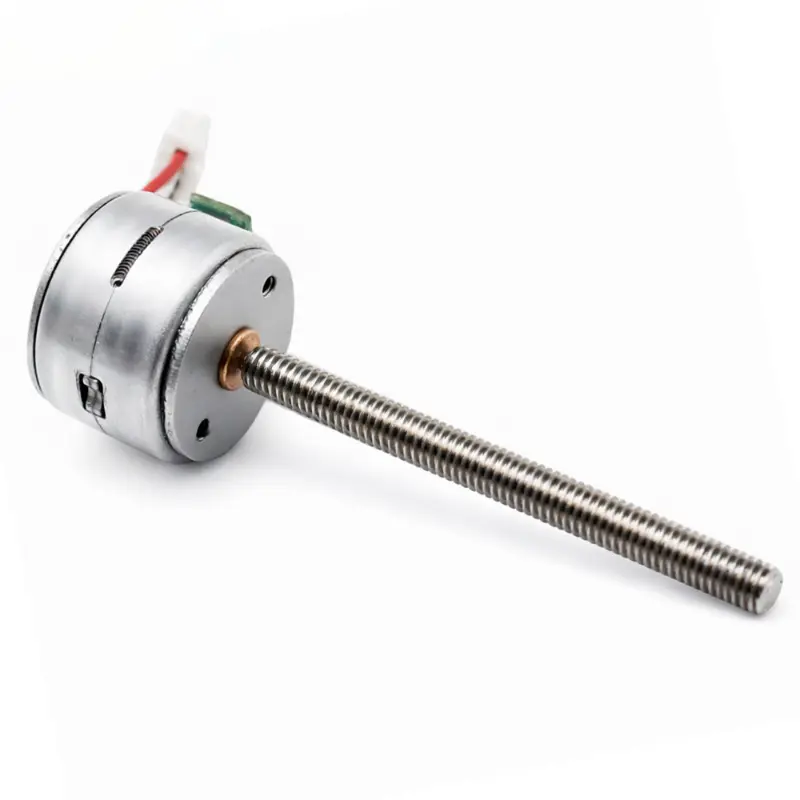
15mm Micro Stepper Motor with Lead Screw, 30mm M3 Shaft, 5V/12V Options
Product Documents & Downloads
| Document Description | File Details |
|---|---|
| KC-15BY25-400 15mm Micro Stepper Motor with 30mm Lead Screw Outline Drawing | PDF · English · 117 KB |
15mm Micro Stepper Motor With Lead Screw
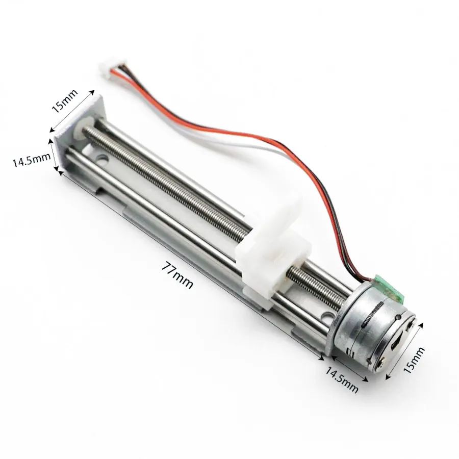
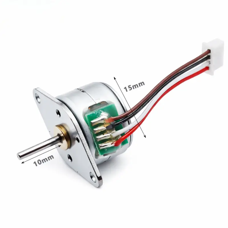
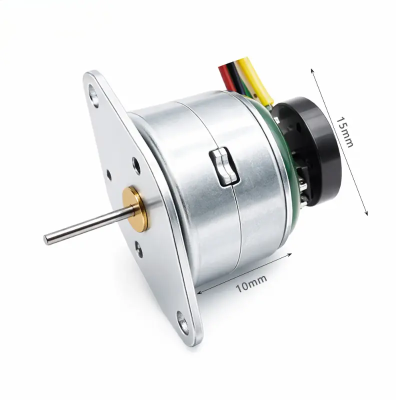
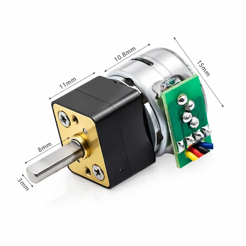
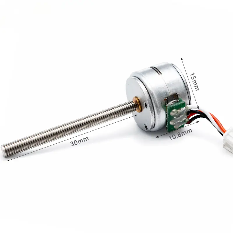
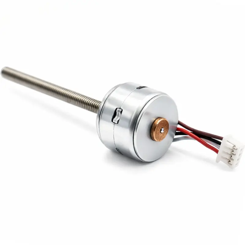
The KC-15BY25-400 micro stepper motor with lead screw combines a 15 mm permanent magnet stepper motor with an M3 threaded shaft for controlled rotary-to-linear motion. The standard drawing shown here uses a 30 ± 0.1 mm screw and does not include a slide, guide rail, gearbox, or integrated traveling nut.
Electrical And Motion Specifications
| Parameter | Specification |
|---|---|
| Brand | Kechen Motor |
| Model | KC-15BY25-400 |
| Product Series | KC-15BY |
| Motor Type | Permanent magnet stepper motor |
| Configuration | 2-phase, 4-wire bipolar |
| Rated Voltage | 5.0 V DC / 12.0 V DC |
| Step Angle | 18° (20 full steps per revolution) |
| Screw Lead | 0.5 mm / 1.0 mm per revolution |
| Linear Travel Per Full Step | 0.025 mm / 0.05 mm typical |
| Maximum Thrust | 1.0–2.5 kgf, depending on configuration and load |
| Phase Resistance | 10–50 Ω, depending on voltage and winding configuration |
| Motor Weight | 15 g |
Mechanical And Connection Specifications
| Parameter | Specification |
|---|---|
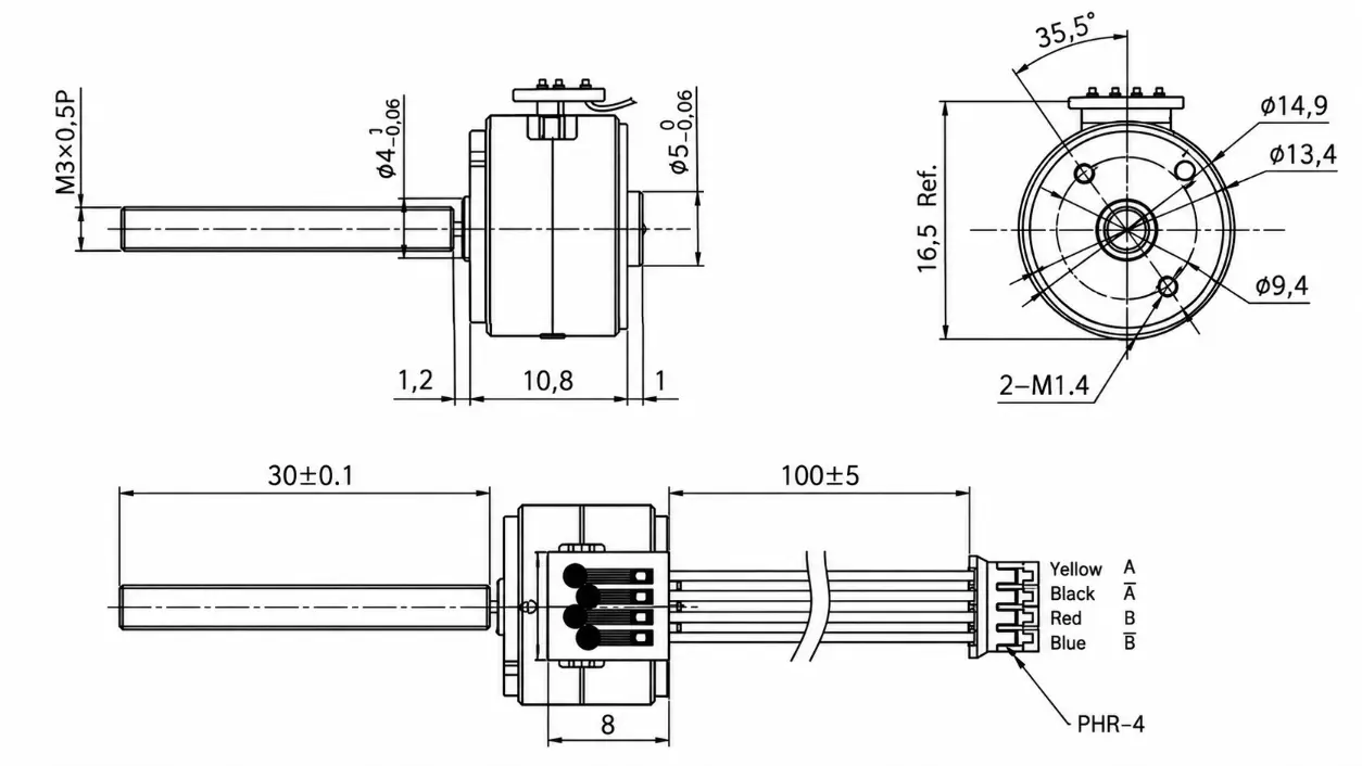
| Motor Diameter | 15 mm nominal |
| Outer Diameter | 14.9 mm |
| Housing Diameter | 13.4 mm |
| Motor Body Length | 10.8 mm |
| Body End Extension | 1 mm |
| Front Mounting Section | 1.2 mm |
| Lead Screw Type | M3 threaded lead screw |
| Lead Screw Thread | M3 × 0.5 |
| Lead Screw Diameter | 3 mm |
| Standard Screw Length | 30 ± 0.1 mm |
| Optional Screw Lengths | 20 mm / 30 mm / 50 mm; custom lengths subject to confirmation |
| Front Shaft Section | 4 mm, −0.06 mm tolerance |
| Rear Shaft Section | 5 mm, −0.06 mm tolerance |
| Mounting Holes | 2 × M1.4 |
| Mounting Hole PCD | 9.4 mm |
| Mounting Angle | 35.5° |
| Reference Overall Height | 16.5 mm |
| PCB Length | 8 mm |
| Lead Wire Length | 100 ± 5 mm |
| Connector | PHR-4, 4-pin |
| Phase A Wiring | Yellow: A / Red: A− |
| Phase B Wiring | Black: B / Blue: B− |
| Motor Connection | Bipolar 4-wire |
KC-15BY25-400 Dimension Drawing
15 mm stepper motor with lead screw mechanical dimensions for product integration.
Engineering Advantages
Small Mechanical Envelope
The 15 mm motor body is suitable for mechanisms where available installation space limits conventional stepper motor sizes.
Direct Threaded-Shaft Output
The M3 screw can convert motor rotation into linear displacement when paired with a compatible nut, guide, and anti-rotation mechanism.
Multiple Screw Configurations
Available screw lengths and lead options allow the motor configuration to be matched to travel, resolution, and mechanism requirements.
Bipolar Drive Configuration
The 2-phase, 4-wire winding supports bipolar stepper driving and can be evaluated with the customer’s required control electronics.
Configuration And Application Notes
This 15mm stepper motor with lead screw is supplied as a motor-and-threaded-shaft assembly rather than a complete linear stage. Linear motion depends on the mating nut, external guide structure, anti-rotation arrangement, drive current, operating speed, and applied load.
Voltage, phase resistance, thrust, screw length, and screw lead represent available configurations rather than one universal winding specification. Final electrical and mechanical parameters should be confirmed against the approved sample for the intended project.
Payment
Shipping
KC-15BY25-400 FAQ
Is The KC-15BY25-400 A Complete Linear Actuator?
No. The product consists of a stepper motor and threaded lead screw. A mating nut, guide mechanism, and anti-rotation structure are required to produce controlled linear movement in the final assembly.
What Lead Screw Is Used On The Standard Drawing?
The illustrated KC-15BY25-400 configuration uses an M3 × 0.5 threaded lead screw with a length of 30 ± 0.1 mm.
Can The Lead Screw Length Be Customized?
Yes. The supplied product information includes 20 mm, 30 mm, and 50 mm screw configurations, while other lengths require confirmation according to the mechanical design.
How Is Linear Travel Per Step Determined?
Linear travel is calculated from the screw lead and the motor’s 18° full-step angle. The listed configurations correspond to typical travel values of 0.025 mm or 0.05 mm per full step.
Is The Maximum Thrust Fixed At 2.5 kgf?
No. The supplied range is 1.0–2.5 kgf. Actual thrust depends on winding selection, drive conditions, screw configuration, speed, mechanical efficiency, and operating load.
Should The 5 V And 12 V Versions Use The Same Winding?
Not necessarily. Voltage and phase resistance vary with the winding configuration, so the required version should be confirmed according to the driver, available supply voltage, operating point, and approved sample.