

Micro Motor Blogs
NEMA 17 Stepper Motor Specifications Explained
NEMA 17 Stepper Motor Specifications Explained
Selecting a NEMA 17 stepper motor for a 3D printer, CNC router, or robotic actuator begins with the frame size, yet the frame alone provides no indication of whether the system achieves target feed rates or maintains position under load. The nema 17 stepper motor specifications that govern real-world performance include rated current per phase, winding inductance, holding torque, detent torque, and thermal limits—and misinterpreting any of these values frequently causes missed steps, excessive winding temperature, or insufficient torque at the operating speed. This article examines each specification against empirical machine behavior, offers selection criteria derived from torque-speed curves, and addresses common errors found in supplier datasheets.
Physical Dimensions and Mechanical Interface
The NEMA 17 frame, as defined by the National Electrical Manufacturers Association, specifies a mounting face of 1.7 inches × 1.7 inches, which equals 42.3 mm × 42.3 mm in metric terms. The bolt hole pattern uses a 31 mm pitch circle diameter with four M3 threaded holes, ensuring interchangeability across most manufacturers. However, mechanical compatibility involves more than the flange. Body lengths for NEMA 17 motors commonly range from 34 mm to 60 mm, and this length directly affects rotor inertia and maximum holding torque. A longer stack—such as 48 mm or 60 mm—adds magnetic laminations and a longer rotor, increasing both torque output and rotational inertia. Systems requiring high acceleration and frequent direction changes, such as a direct-drive extruder in a filament printer, benefit from a shorter body to reduce inertia, whereas a belt-driven gantry with high static friction typically requires the higher torque of a longer stack.
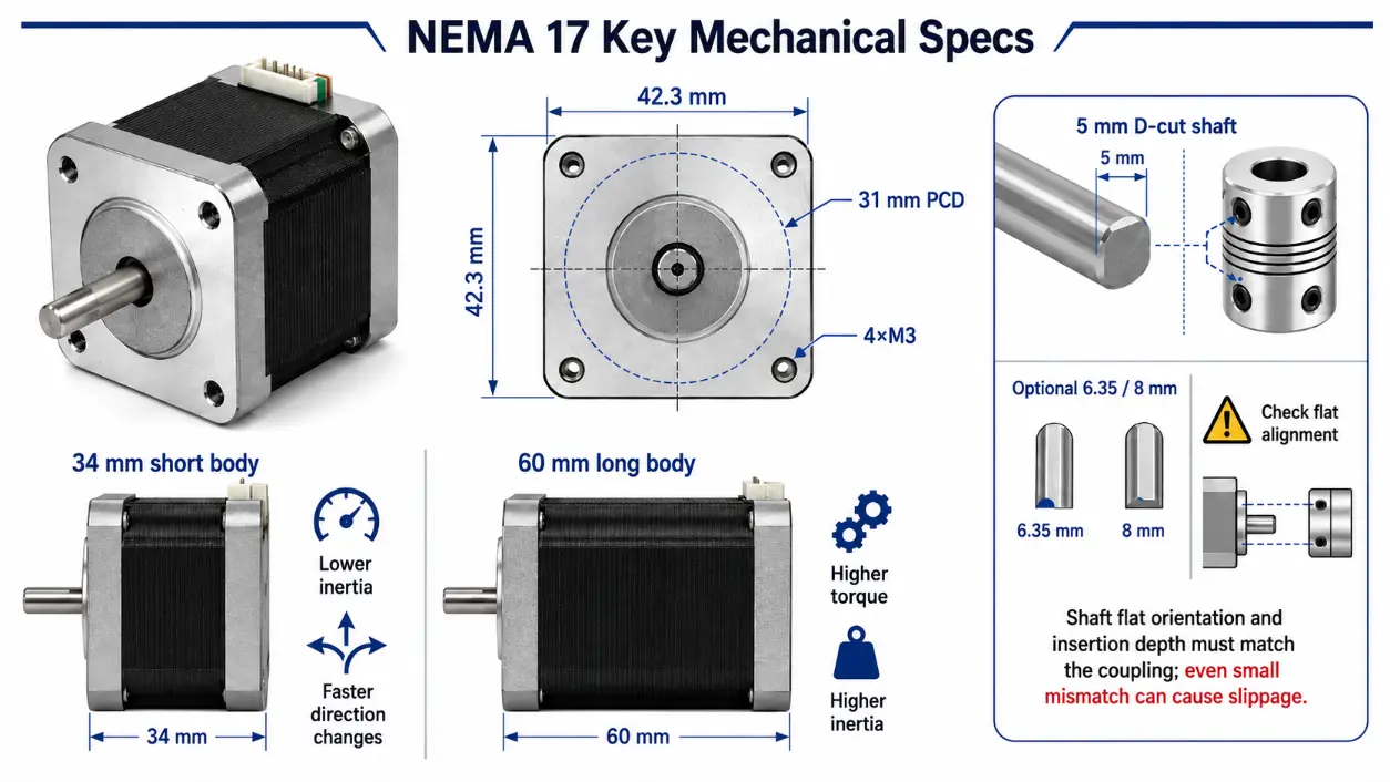
Shaft diameter is another decisive mechanical parameter. The standard configuration is a 5 mm shaft with a single flat (D‑cut) for set‑screw couplings. Alternative diameters of 6.35 mm (¼ inch) and 8 mm are available for higher radial loads or when standard shaft components are not suitable. When reviewing nema 17 stepper motor specs, the shaft length and the flat position relative to the shaft end must be checked against the coupling or pulley drawing. A 0.5 mm deviation in insertion depth can cause the set screw to miss the flat, leading to slippage under load. For drop‑in replacements, the nema 17 specification for flange, shaft diameter, and flat orientation must match exactly; otherwise, the mechanical mount requires redesign.
Electrical Parameters and Their Influence on Performance
Electrical ratings constitute the core of the nema 17 stepper motor specifications, and they are frequently misinterpreted due to inconsistent datasheet presentation. The rated current per phase for bipolar NEMA 17 motors typically falls between 0.5 A and 2.5 A. This figure represents the maximum direct current that the windings can sustain without exceeding the insulation thermal class. Operating below this current reduces holding torque proportionally but lowers heat generation—a trade‑off that can be advantageous in enclosed enclosures without forced air. Conversely, if the driver current limit is set below the motor’s rated current, the motor never reaches its specified torque, regardless of the supply voltage.
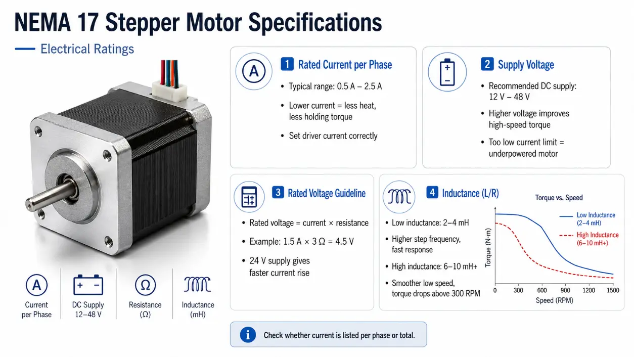
Voltage ratings are seldom given as a single fixed number; instead, datasheets provide a recommended DC supply range, typically 12 V to 48 V. The supply voltage affects the current rise time in the windings. Higher voltages enable the driver to overcome winding inductance more quickly, improving torque at higher step rates. However, increased supply voltage also raises switching losses in the driver and subjects motor insulation to higher voltage transients. A commonly used engineering guideline is to select a supply voltage at least 5 to 10 times the motor’s rated voltage (rated current × winding resistance) to obtain adequate high‑speed performance. For example, a motor with 3 Ω resistance and 1.5 A rated current has a rated voltage of 4.5 V; a 24 V supply provides a substantial margin for rapid current switching, though the exact multiplier depends on the driver topology and the motor’s inductance.
Winding inductance, expressed in millihenries (mH), is often overlooked in nema 17 stepper motor specs. Inductance determines the electrical time constant (L/R). Low‑inductance motors (approximately 2–4 mH) reach the set current faster, allowing higher step frequencies—suitable for extruder drives in 3D printers, where retraction moves can exceed several thousand steps per second. High‑inductance motors (6–10 mH or more) deliver smoother low‑speed operation and higher holding torque but exhibit a more pronounced torque drop above 300 RPM. When comparing nema 17 stepper motor specs from different vendors, verify whether the current rating is expressed “per phase” or as “total” for the entire motor. Some suppliers list total current, which is half the per‑phase value; using that figure for driver configuration results in an underpowered setup.
Torque Characteristics: Holding, Pull‑in, and Pull‑out
Holding torque, measured in ounce‑inches (oz‑in) or Newton‑centimeters (N‑cm), is the maximum static torque the motor produces with rated current applied to both phases. Typical values for NEMA 17 motors range from 30 oz‑in (approximately 21 N‑cm) for short‑body variants to 80 oz‑in (56 N‑cm) for extended‑length versions. While holding torque is a convenient specification for comparison, it does not predict dynamic performance. A motor with high holding torque but high inductance may stall at 200 RPM, whereas a motor with moderate holding torque and low inductance may operate reliably at 500 RPM, depending on the supply voltage and driver settings.
The pull‑out torque curve, provided in reputable datasheets, plots available torque against step rate (or speed in RPM) at a given supply voltage and current. This curve is the only reliable basis for selection when the application involves continuous motion rather than static holding. In a CNC router, for instance, the axis motors must overcome friction, cutting forces, and acceleration loads at traverse speeds. Selecting a motor solely by holding torque often leads to undervoltage or undercurrent conditions that reduce the actual pull‑out torque by 40 % or more at the required speed, depending on the motor’s inductance and the driver’s current regulation. For extruder drives in filament printers, where retraction rates frequently exceed 50 mm/s, the motor must sustain torque at approximately 300–400 RPM. A low‑inductance motor with a 24 V supply typically outperforms a high‑inductance motor at those speeds, even if the latter has a 20 % higher holding torque.
Detent torque, also called cogging torque, arises from permanent‑magnet interaction with stator teeth when the motor is unpowered. Detent torque is usually less than 10 % of holding torque, yet it affects low‑speed smoothness and microstepping accuracy. For applications requiring sub‑degree positioning—such as pan‑tilt mechanisms or optical alignment stages—a lower detent torque is advantageous, though this parameter is rarely listed. An empirical test with a torque gauge is the most direct method to quantify it.
Step Angle, Accuracy, and Microstepping Considerations
The standard step angle for NEMA 17 motors is 1.8°, producing 200 full steps per revolution. Some variants offer 0.9° (400 steps/rev) for increased resolution and smoother low‑speed motion, but they generally deliver slightly lower torque because of the increased number of pole pairs, though the difference varies with design. The step‑angle accuracy for a standard 1.8° motor is specified as ±5 % of the step angle, non‑cumulative—each step can deviate within that tolerance, but errors do not accumulate over successive steps. This accuracy is sufficient for most open‑loop applications where the mechanical load stays below the pull‑out torque.
Microstepping, implemented by the driver, divides each full step into smaller increments (1/2, 1/4, 1/8, up to 1/256). While microstepping reduces vibration and audible noise, it does not improve absolute positional accuracy beyond the motor’s inherent step‑angle tolerance. The theoretical resolution increases, but the actual positioning error remains bounded by the full‑step accuracy. For example, in a 3D printer with a 20‑tooth pulley and 2 mm belt pitch, a 1.8° motor with 1/16 microstepping yields a theoretical resolution of 0.00625 mm per microstep, yet the repeatable accuracy is limited by the motor’s ±5 % step error and mechanical backlash. Consequently, selecting a driver with very high microstep division does not compensate for a poorly matched set of nema 17 motor specifications.
Thermal Behavior and Environmental Constraints
Thermal management directly influences the service life and reliability of NEMA 17 motors. The maximum allowable coil temperature is determined by the insulation class—Class B (130 °C) and Class F (155 °C) are common. In practice, the motor housing temperature should not exceed 80–90 °C during continuous operation, as the internal coil temperature may be 15–20 °C higher than the housing. Exceeding the thermal limit permanently reduces flux density in neodymium magnets, decreasing torque, and degrades the enamel insulation, potentially causing inter‑turn shorts.
For systems operating in ambient temperatures above 40 °C, derating the current by 20–30 % is a standard practice in motion control to keep the coil temperature within limits. Enclosed enclosures without airflow exacerbate heat buildup; active cooling via a fan or a heat sink attached to the motor frame is recommended for duty cycles exceeding 60 %. Most NEMA 17 motors carry an IP40 rating, offering protection against solid objects larger than 1 mm but no defense against water ingress. Sealed variants with IP54 or higher are available for dusty or wash‑down environments, though they typically exhibit higher thermal resistance due to the encapsulating material.
Practical Selection Procedure Based on Application
A systematic selection process for a NEMA 17 motor starts with defining the load parameters. Calculate the required torque at the maximum operating speed, including acceleration torque, friction torque, and any external force. For a belt‑driven linear axis, the required torque equals the product of belt tension and pulley radius, plus the inertia torque from the motor rotor and the load reflected to the motor shaft. Once the torque‑speed point is established, plot it against the pull‑out curves of candidate motors. The selected motor should provide at least a 20 % margin above the required torque at that speed to accommodate supply voltage variations and temperature effects.
Next, match the motor’s rated current to the driver’s current capability. A driver rated for 2.0 A peak cannot safely drive a motor requiring 2.5 A per phase. The supply voltage should be chosen within the driver’s acceptable range—preferably at the higher end to improve high‑speed performance—while ensuring that the motor’s insulation voltage rating is not exceeded. Wiring configuration—whether the motor has 4, 6, or 8 leads—determines the connection method (bipolar series, bipolar parallel, or unipolar). Nearly all modern NEMA 17 motors are bipolar with 4 leads, but some 8‑lead models permit flexible series/parallel connection.
Finally, evaluate rotor inertia. A longer body motor has higher rotor inertia, which increases the total reflected inertia and may reduce acceleration rates. For applications requiring frequent starts and stops, a shorter motor with lower inertia can achieve faster settling times even if its holding torque is slightly lower. When sourcing a replacement, the nema 17 stepper specs for shaft diameter, flat length, and bolt hole depth must match the existing mechanical assembly to avoid costly modifications.
Application Examples and Contextualized Specifications

In 3D printers, the extruder motor experiences rapid directional changes during retraction and priming. A motor with a body length of 40 mm, rated current of 1.2–1.5 A, and inductance below 4 mH is typically preferred. Some leading printer manufacturers use motors that emphasize low inductance over peak holding torque, because the extruder rarely demands full holding torque but frequently operates at step rates exceeding 400 steps per second. For the X/Y axes on a Cartesian printer, a 42–48 mm motor with moderate inductance provides sufficient torque for belt‑driven carriages at speeds of 150–200 mm/s.
CNC laser engravers, which maintain constant belt tension and undergo occasional acceleration, benefit from longer 60 mm motors with holding torque above 50 oz‑in. The higher torque resists belt stretch and preserves positional accuracy during engraving passes. The increased rotor inertia requires acceleration limiting to prevent missed steps, which is acceptable for laser applications because rapid direction changes occur less frequently than in 3D printing. Robotic arms often demand smooth low‑speed motion, making 0.9° step‑angle motors attractive; these retain the same frame dimensions and nema 17 specs for flange and shaft, but their electrical parameters differ, requiring careful driver tuning.
Interpreting Datasheets and Verifying Specifications
Reliable datasheets from established motor manufacturers include mechanical drawings, torque‑speed curves at multiple supply voltages, thermal resistance data, and inductance values. Generic listings on e‑commerce platforms often omit these details, displaying only a current value and a holding torque figure that may be theoretical rather than measured. For any critical procurement, request the complete nema 17 motor specifications document and verify that the pull‑out curve matches the intended operating speed. Using the full part number to search for the nema 17 stepper motor specifications ensures that the exact revision and manufacturing batch are documented; relying on title keywords alone risks receiving a motor with different electrical characteristics.
To facilitate comparison, the following table summarizes typical parameter ranges for NEMA 17 motors grouped by body length. Note that these values are representative—actual figures vary by manufacturer and specific winding design.
| Body Length | Holding Torque (oz‑in) | Current per Phase (A) | Inductance (mH) | Typical Applications |
|---|---|---|---|---|
| 34 mm | 25–35 | 0.8–1.2 | 2.0–3.5 | Small extruders, light‑duty gantries |
| 40 mm | 35–45 | 1.2–1.8 | 3.0–4.5 | Standard 3D printer axes, filament extruders |
| 48 mm | 45–60 | 1.5–2.2 | 4.0–6.0 | CNC routers, belt‑driven engravers |
| 60 mm | 60–80 | 1.8–2.5 | 5.5–8.0 | Heavy‑load axes, milling tables |
Conclusion
The practical value of understanding nema 17 stepper motor specifications lies in aligning the motor’s electrical and mechanical limits with the system’s dynamic torque demand, supply conditions, and thermal environment—not in maximizing any single parameter.
Frequently Asked Questions
Q1: Is holding torque the most important spec when comparing NEMA 17 motors?
No. Holding torque indicates static force but does not represent torque at operating speed. The pull‑out torque curve at the intended step rate is the decisive criterion. A motor with lower holding torque but lower inductance often outperforms a high‑holding, high‑inductance motor in dynamic applications such as 3D printing or CNC milling.
Q2: Can I use a 48 V supply with any NEMA 17 motor rated for 12 V?
Not without verifying the driver’s switching capability and the motor’s insulation rating. A higher supply voltage improves high‑speed torque but increases current ripple and switching losses. The motor must have an insulation class rated for at least 50 V (most do), but the driver must support the voltage and current settings. Always check the driver’s maximum supply voltage and measure the motor temperature during initial operation.
Q3: Why do two motors with identical printed specs behave differently in my system?
Specifications may be presented under different measurement conditions—for example, holding torque measured at 100 % current vs. 50 % duty cycle, or inductance measured at 1 kHz vs. 1 MHz. Manufacturing tolerances in winding resistance and magnet strength also contribute. For consistent performance, request the actual test report or use a standardized measurement protocol (e.g., ASTM or IEC standards) from the supplier.