

Micro Motor Blogs
NEMA 17 Stepper Motor Size & Dimensions Guide
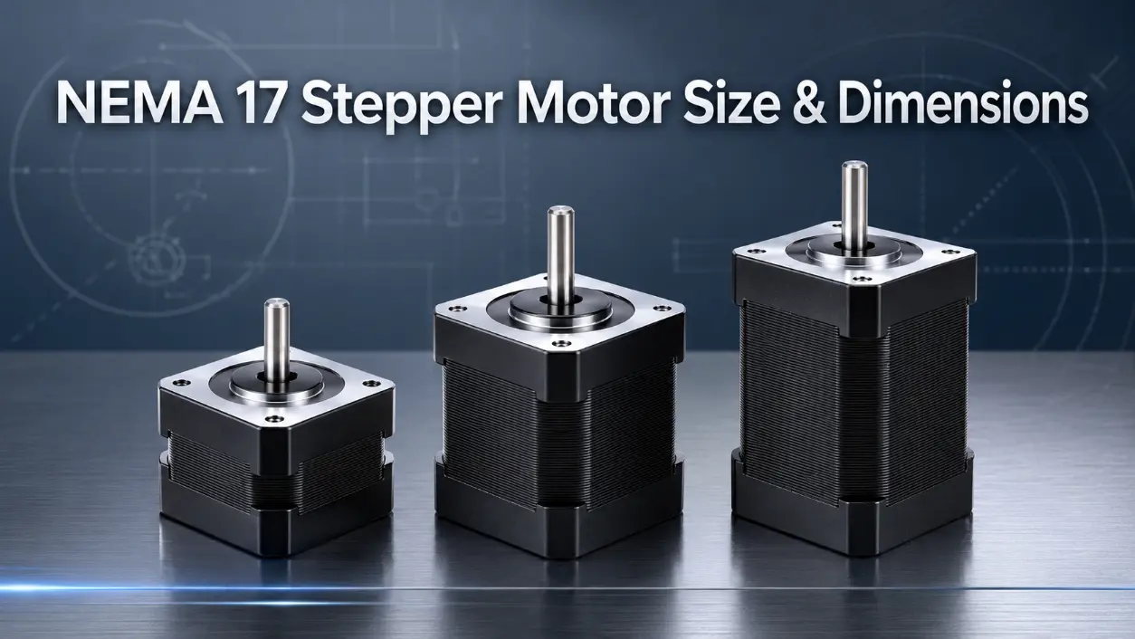
Selecting a hybrid stepper motor for a motion control system begins with the mechanical envelope. The nema 17 stepper motor size is frequently specified in CNC routers, 3D printers, and linear actuator stages, but the “17” designation alone provides insufficient data for mechanical integration. Engineers must evaluate the frame face, body length, shaft configuration, and available technical drawings to ensure proper fit and torque output. This guide defines the physical standards, common variations, and critical measurement points for the NEMA 17 class, with direct reference to the nema 17 frame size and the associated nema 17 42mm mounting interface.
NEMA 17 Frame Standard and Mounting Interface
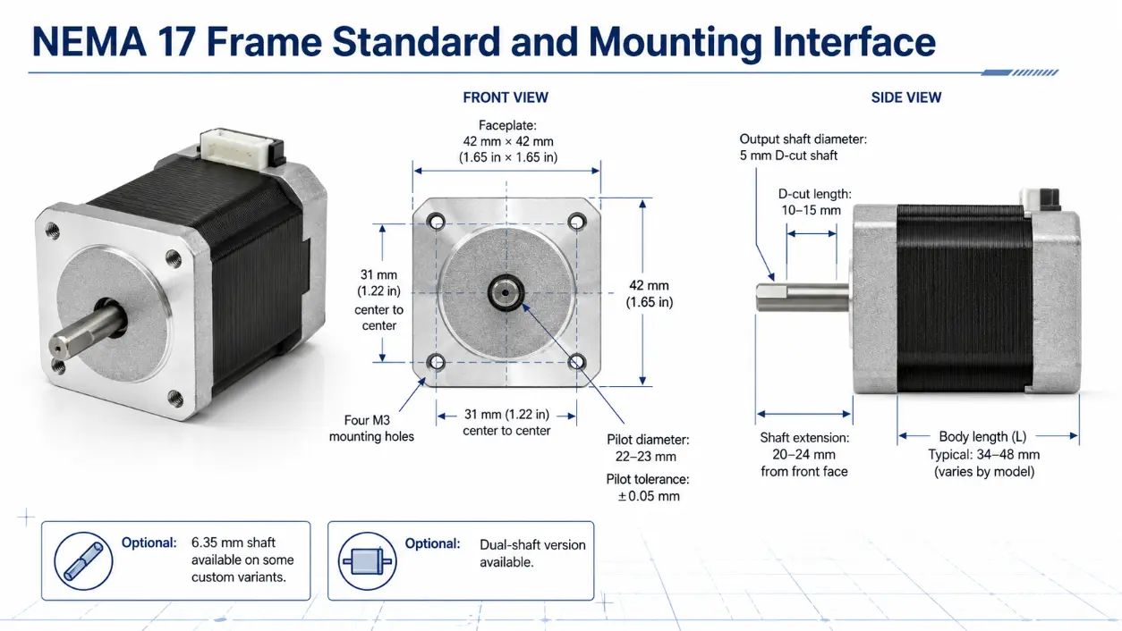
The National Electrical Manufacturers Association (NEMA) establishes frame size designations based on the mounting face dimensions. For the NEMA 17 class, the faceplate measures 42 mm × 42 mm (approximately 1.65 inches per side). This dimension is fixed across all compliant models. The nema 17 frame size directly determines the bolt hole pattern: four M3 mounting holes positioned at the corners of a 31 mm × 31 mm square, measured center to center. This consistent mounting geometry allows interchangeability between suppliers, provided the motor depth does not interfere with adjacent components. The front flange includes a pilot diameter that locates the motor concentric to the mounting surface; typical pilot diameters fall within 22 mm to 23 mm (values sourced from common manufacturer datasheets), with a tolerance of ±0.05 mm specified by many suppliers for alignment in belt-driven or leadscrew-driven systems. This tolerance, while not explicitly defined in the NEMA standard itself, is widely adopted in production drawings to maintain concentricity between the motor shaft and the driven pulley or coupling.
The output shaft is a critical element of the mechanical interface. Most NEMA 17 motors supply a single 5 mm diameter shaft with a flat D-cut ground along one side. The D-cut length generally spans 10 mm to 15 mm from the shaft end, providing a positive locking surface for setscrew-type pulleys or couplings. Some variants offer a 6.35 mm (1/4 inch) shaft—though this configuration is uncommon in standard NEMA 17 production and typically appears in custom orders or specialty models—while others provide a dual-shaft configuration, with the rear shaft extended to accommodate manual knobs or optical encoders. When evaluating a nema 17 stepper motor drawing, always verify the shaft diameter, D-cut orientation, and the shaft extension length—typically 20 mm to 24 mm from the front face—against the coupling manufacturer’s specifications.
Body Length Variations and Torque Implications
While the faceplate and shaft diameter are standardized, the motor body length—often referred to as the stack length—varies significantly. The nema 17 motor dimensions in the axial direction directly correlate with the available winding volume and, consequently, the rated holding torque. A shorter stack motor (approximately 34 mm deep) produces roughly 0.2 N·m of holding torque, suitable for low-load extruder drives or small pan-tilt mechanisms. As the stack length increases to 40 mm–42 mm, the torque rises to approximately 0.4 N·m, commonly found in entry-level 3D printer X/Y axes. Longer stacks in the 48 mm to 52 mm range deliver 0.6 N·m, while the extended 60 mm class can exceed 0.8 N·m. These extended-length motors are frequently applied in CNC milling spindles or pick-and-place gantries where additional torque is required to overcome cutting forces or friction. It should be noted that the torque values listed here are representative typical figures observed across multiple suppliers; actual ratings vary by winding design and drive voltage, and datasheets should always be consulted for the specific model under consideration.
An increase in body length does not change the nema 17 42mm faceplate, but it does alter the overall envelope. Designers must account for the total depth, including any clearance required for cable connectors at the rear. Furthermore, longer stators exhibit higher phase inductance, which shifts the torque-speed curve toward lower maximum step rates. To achieve rated torque at higher speeds, the driver must supply a proportionally higher bus voltage. Therefore, the selection of a specific nema 17 stepper motor size must balance the required holding torque, the available axial space, and the driver’s voltage capability.
Standard Body Length vs. Torque Table
| Stack Classification | Body Length (mm) | Typical Holding Torque (N·m) | Common Application |
|---|---|---|---|
| Single Stack | ~34 | 0.2 | Extruder drives, light-duty positioning |
| Double Stack | 40–42 | 0.4 | 3D printer axes, small CNC routers |
| Triple Stack | 48–52 | 0.6 | CNC milling, pick-and-place gantries |
| Extended Stack | 58–60 | >0.8 | Heavy-duty linear stages, industrial feeders |
Technical Drawing and Dimensional Data Interpretation
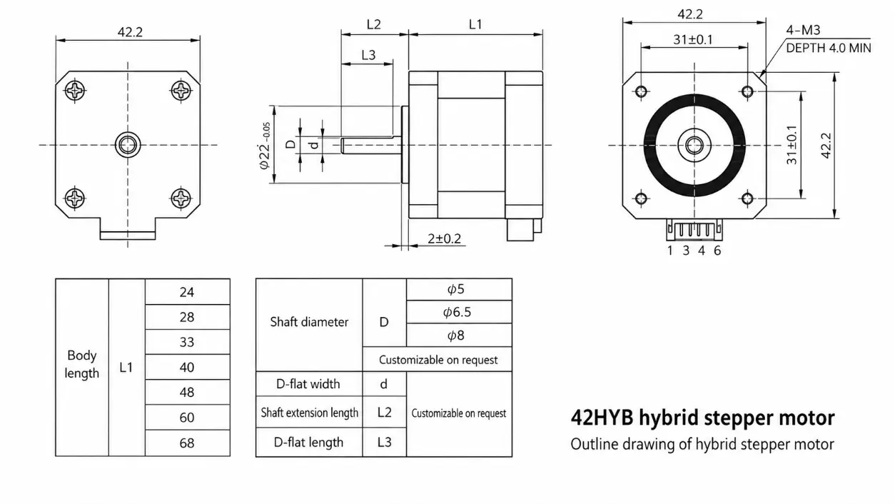
Accurate mechanical integration relies on the nema 17 drawing provided by the manufacturer. A comprehensive nema 17 stepper motor drawing includes three standard orthographic views. The front view details the 42 mm square flange, the central pilot diameter, and the mounting hole pattern with true position tolerances. The side view provides the overall length (dimension L), the shaft extension length, and the D-cut flat dimension. The rear view, if included, shows the connector pinout or lead wire exit location, which is essential for cable management in confined assemblies. For example, when mounting a NEMA 17 motor in a delta 3D printer carriage, the side view allows the designer to verify that the motor body length (dimension L) does not interfere with the belt path or the effector platform’s range of motion.
One common engineering oversight involves confusing the mechanical drawing with the electrical wiring diagram. The mechanical nema 17 drawing does not indicate which wire is A+ or B+; it only provides physical dimensions. The wiring diagram is typically a separate document. Another frequent misinterpretation relates to the D-cut orientation. The D-cut flat is referenced to the shaft centerline, but its angular position relative to the mounting holes is rarely specified on standard drawings. For applications requiring a specific pulley setscrew orientation, the designer must either specify a custom shaft keying or use a shaft coupling that accommodates angular misalignment.
Integrated Variants and Accessory Impact on Dimensions
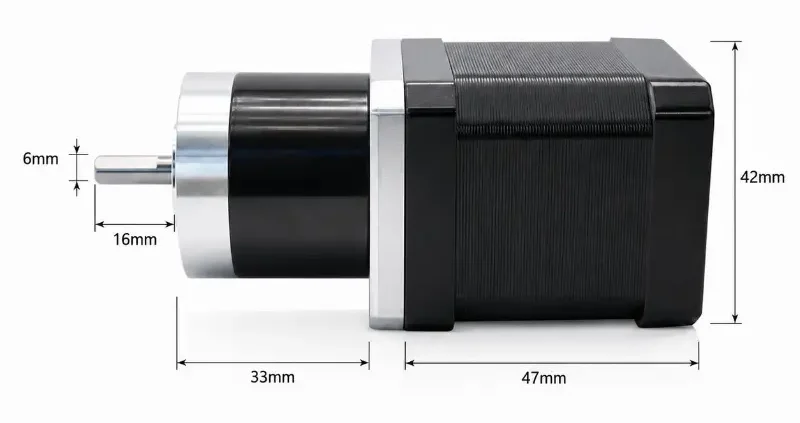
The nema stepper size classification remains anchored to the 42 mm faceplate, but integrated assemblies can substantially change the total installed length. Motors fitted with a T8 leadscrew, for example, replace the output shaft with a threaded rod that extends beyond the motor front face. The effective nema 17 motor dimensions in such configurations must include the screw length plus any traveling nut clearance. Similarly, planetary gearboxes attached to the motor front increase the axial length by 30 mm to 50 mm, depending on the gear ratio. When specifying a geared NEMA 17, the overall nema 17 stepper motor size is the sum of the motor stack length and the gearbox length. This cumulative dimension frequently interferes with side panels in benchtop equipment, requiring careful layout planning.
Connector options also influence the physical envelope. Motors supplied with bare leads occupy the least space, but those fitted with 6-pin JST or Molex connectors have rear housings that extend 5 mm to 10 mm beyond the motor flange. Ribbon cable assemblies, often used in multi-axis systems, may exit radially from the side, demanding additional clearance in the X or Y direction. Engineers should incorporate these connector protrusions into the initial mechanical clearance analysis, rather than relying solely on the motor body depth.
Step-by-Step Sizing Procedure for Application Integration
To correctly specify a nema 17 stepper motor size for a given application, follow these four steps:
- Measure available axial depth: Determine the maximum allowable motor length from the mounting face to the nearest obstruction (e.g., panel, cover, or adjacent component). Subtract 2 mm–3 mm for tolerance and air circulation.
- Define required holding torque: Calculate the load torque at the motor shaft, including friction and acceleration components. Select the shortest stack length that meets or exceeds this value. A longer stack than necessary increases cost and consumes space without functional benefit.
- Check shaft type and extension: Confirm whether a standard 5 mm D-shaft suffices, or if a 6.35 mm shaft or dual-shaft design is required for encoder feedback. Verify that the coupling or pulley manufacturer recommends the same shaft diameter and flat length.
- Review connector and wire exit: Ensure that the selected motor’s connector housing or cable exit does not interfere with cable carriers, panel cutouts, or moving parts.
Throughout this process, the nema 17 motor dimensions listed in the datasheet should be treated as nominal values. Production tolerances on length typically range from ±0.5 mm to ±1.0 mm. For high-density systems, request the supplier’s 3D CAD model and cross-check it with the physical prototype. Relying on generic step files from online repositories can lead to discrepancies because these models often omit the rear shaft or connector details. Always reference the specific nema 17 drawing that accompanies the motor part number under consideration.
Comparative Sizing: NEMA 17 vs. Adjacent Frame Classes
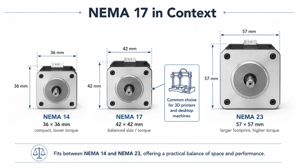
Understanding the nema 17 frame size in the context of other NEMA standards aids in selecting the optimal motor class. The NEMA 14 frame measures 36 mm × 36 mm, offering a smaller footprint suitable for micro-robotics but limited to approximately 0.1 N·m holding torque. The NEMA 23 frame, at 57 mm × 57 mm, provides up to 2.5 N·m or more, but its larger flange and bolt pattern demand more panel space. The nema 17 42mm faceplate sits between these two, accommodating most desktop machines that require moderate torque without consuming excessive area. A 3D printer, for instance, benefits from the NEMA 17’s balance: it drives the bed or extruder with enough force to overcome filament resistance, yet leaves room for multiple axes in a enclosure.
The nema stepper size alone does not determine motor power; the stack length and winding current handle that role. However, the frame size does establish the bearing span, shaft diameter, and mounting stiffness. For applications with high radial loads, such as belt-driven axes with tensioned timing belts, a NEMA 23 motor might be preferred despite the larger footprint, because its front bearing can withstand greater side loads. Conversely, in applications where space is the primary constraint, selecting a longer NEMA 17 stack is often more practical than moving up to a NEMA 23 and redesigning the surrounding structure.
Frequently Asked Questions
Q1: Does the NEMA 17 designation guarantee the motor body length?
No. NEMA 17 only specifies the faceplate dimensions (42 mm × 42 mm) and the mounting hole pattern. Body length varies from 34 mm to 60 mm depending on the stack size. Always refer to the mechanical drawing for the exact depth.
Q2: Are all NEMA 17 motors electrically compatible with the same driver?
Not necessarily. The electrical phase current and winding resistance differ across models. A short-stack motor may require 1.0 A per phase, whereas an extended-stack motor could need 2.0 A or higher. Using an undersized driver leads to torque derating and potential stall conditions. The nema 17 stepper motor drawing does not include electrical parameters; these are found in the electrical specification table.
Q3: Is the 5 mm shaft diameter a mandatory standard for all NEMA 17 motors?
While 5 mm is the most prevalent shaft diameter, some manufacturers offer 6.35 mm (1/4″) shafts for higher torque capacity, particularly in extended-length models. However, such configurations are uncommon in standard production; the vast majority of off-the-shelf NEMA 17 motors use a 5 mm shaft. Custom shaft configurations with metric or imperial dimensions are available through specialty suppliers. Always verify the shaft size on the nema 17 drawing before ordering mating components.
Conclusion
The NEMA 17 stepper motor provides a standardized 42 mm mounting interface, but its axial length, shaft configuration, and connector style must be carefully matched to each application’s spatial and torque requirements through a thorough review of the manufacturer’s technical drawings.