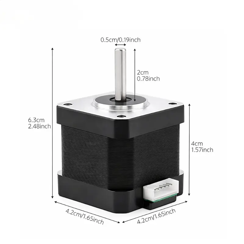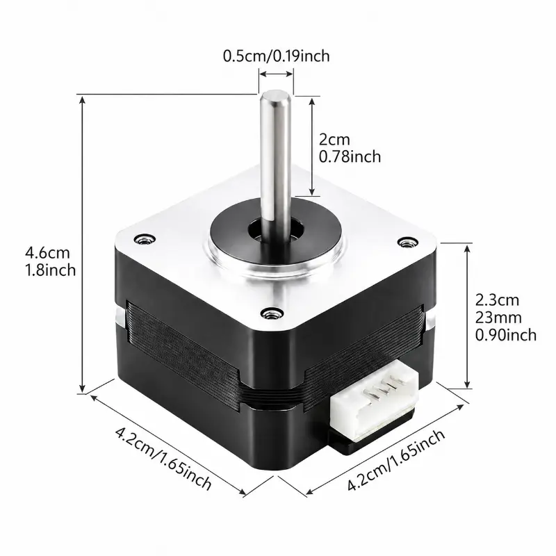
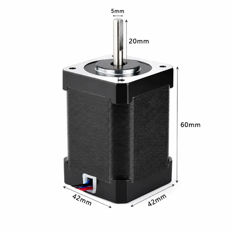
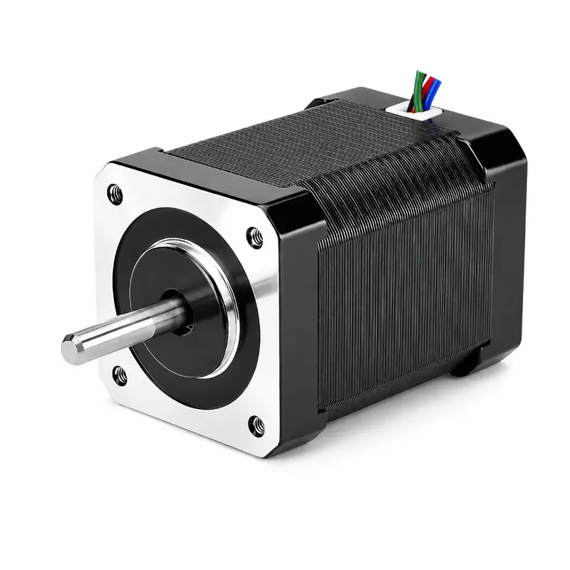

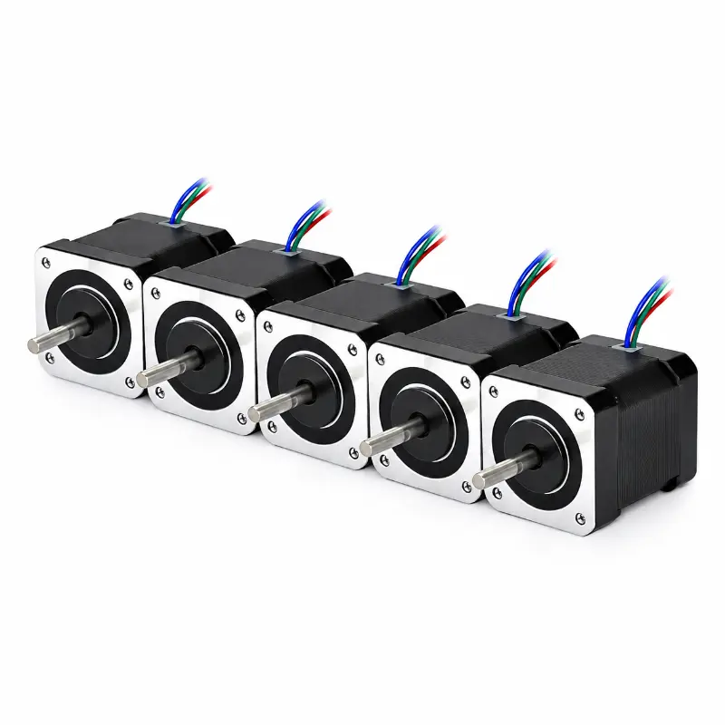
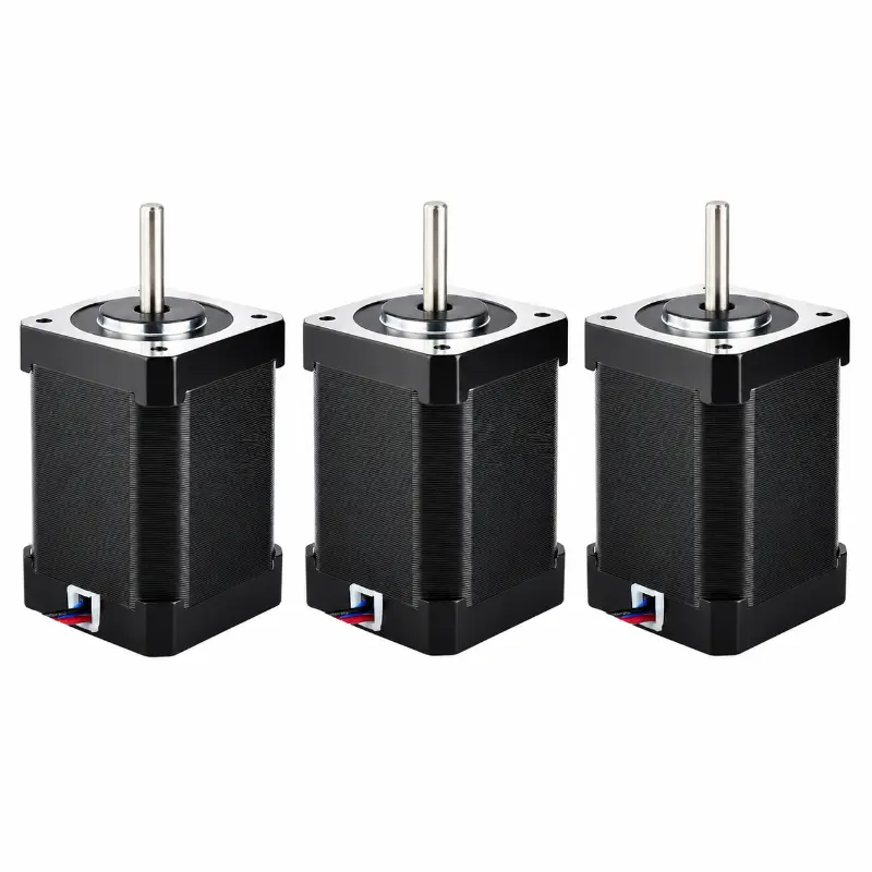
NEMA 17 60mm Stepper Motor Series with 0.9° Step Angle and 2A Current
Related Product Documents & Downloads
| Document Description | File Details |
|---|---|
| NEMA 17 60mm Stepper Motor Datasheet | PDF · English · 222 KB |
KC-42HYB60 NEMA 17 60mm Stepper Motor Technical Overview
The KC-42HYB60 is a 42.2 mm frame, two-phase hybrid stepper motor designed around a 60 mm motor body and a 0.9° step angle. This configuration is intended for motion systems where engineers require a NEMA 17 mechanical interface together with finer native angular resolution than a conventional 1.8° motor. The nema 17 60mm stepper motor uses a D-shaft configuration and is specified with a rated current of 2 A, 1.8 Ω phase resistance, 5.2 mH inductance, and 6.7 kg·cm holding torque. Its mechanical format supports integration into positioning equipment, linear motion assemblies, machine modules, laboratory equipment, automation mechanisms, and other controlled motion systems requiring a defined 42 mm class mounting interface.
Engineering Positioning And Motor Configuration
With a 42.2 × 42.2 mm frame and 60 mm body length, this nema 17 60mm configuration provides a longer magnetic stack than shorter 24 mm, 33 mm, 40 mm, and 48 mm models in the same product family. The KC-42HYB60 combines a 0.9° native step angle with a two-phase construction, making it suitable for applications that require smaller angular increments before electronic microstepping is applied. The electrical specification should be matched to an appropriate current-controlled bipolar stepper driver. Although the rated voltage range is listed as 3–24 V DC, driver selection, supply voltage, acceleration profile, load inertia, winding current, operating speed, and thermal conditions should be evaluated together during system integration.
KC-42HYB60 Electrical And Mechanical Specifications
| Parameter | Specification |
|---|---|
| Product Model | KC-42HYB60 |
| Product Type | NEMA 17 hybrid stepper motor |
| Shaft Type | D shaft |
| Frame Size | 42.2 × 42.2 mm |
| Motor Body Length | 60 mm |
| Shaft Length | 40 mm |
| Step Angle | 0.9°/step |
| Number Of Phases | 2 phases |
| Rated Current | 2 A |
| Phase Resistance | 1.8 Ω |
| Phase Inductance | 5.2 mH |
| Holding Torque | 6.7 kg·cm |
| Rated Voltage Range | 3–24 V DC |
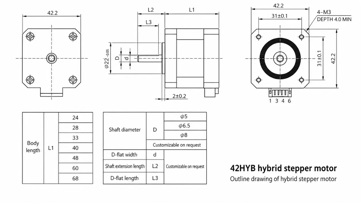
| Mounting Hole Spacing | 31 ± 0.1 mm |
| Mounting Holes | 4 × M3 threaded holes |
| Thread Depth | 4.0 mm minimum |
| Front Boss Diameter | Ø22 mm (+0 / −0.05) |
| Shaft Diameter Options | Ø5 mm / Ø6.5 mm / Ø8 mm |
| D-Shaft Width | Customizable |
| Output Shaft Length | Customizable |
| D-Shaft Flat Length | Customizable |
| Available Motor Body Lengths | 24 mm / 28 mm / 33 mm / 40 mm / 48 mm / 60 mm / 68 mm |
NEMA 17 Hybrid Stepper Motor Series Performance Comparison
| Model | Resistance | Inductance | Step Angle | Phases | Rated Current | Holding Torque | Shaft Length | Motor Body Length |
|---|---|---|---|---|---|---|---|---|
| KC-42HYB24 | 3.6 Ω | 4.1 mH | 1.8°/step | 2 phases | 1 A | 1.8 kg·cm | 20 mm | 24 mm |
| KC-42HYB33 | 3.8 Ω | 6.3 mH | 1.8°/step | 2 phases | 1.5 A | 4.4 kg·cm | 144 mm | 33 mm |
| KC-42HYB40 | 1.7 Ω | 3.5 mH | 1.8°/step | 2 phases | 1 A | 3.4 kg·cm | 20 mm | 40 mm |
| KC-42HYB48 | 5.8 Ω | 10.5 mH | 1.8°/step | 2 phases | 1.4 A | 7.6 kg·cm | 22.5 mm | 48 mm |
| KC-42HYB60 | 1.8 Ω | 5.2 mH | 0.9°/step | 2 phases | 2 A | 6.7 kg·cm | 40 mm | 60 mm |
| KC-42HYB68 | 2.7 Ω | 7 mH | 1.8°/step | 2 phases | 1.5 A | 8.7 kg·cm | 22 mm | 68 mm |
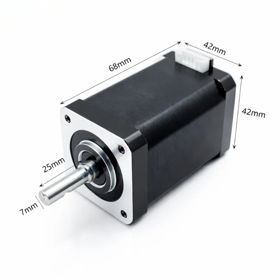
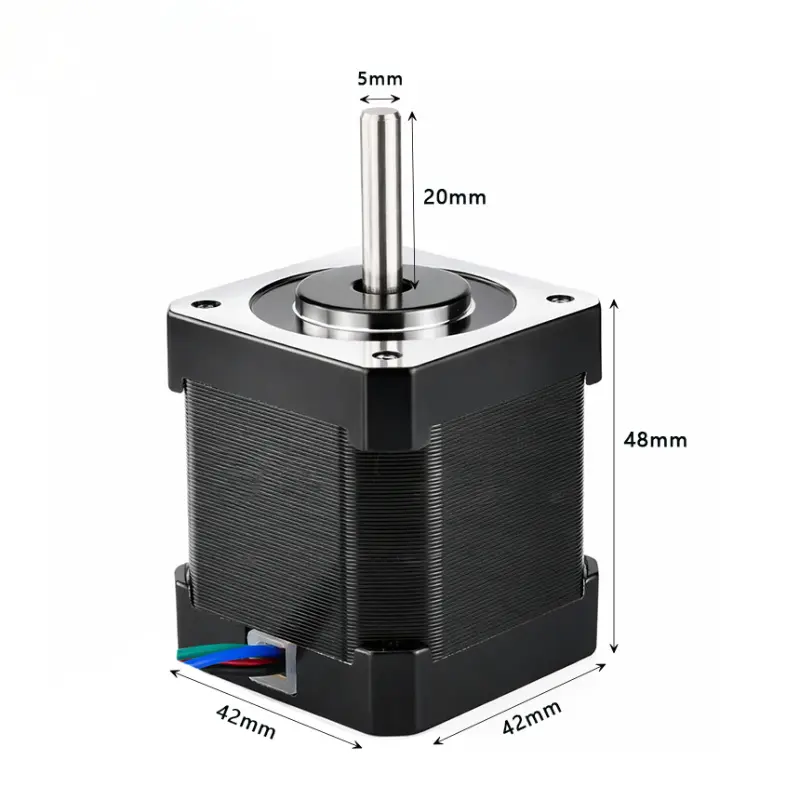
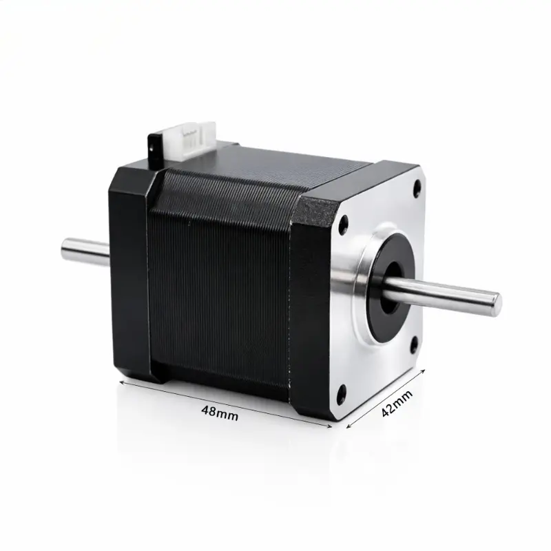
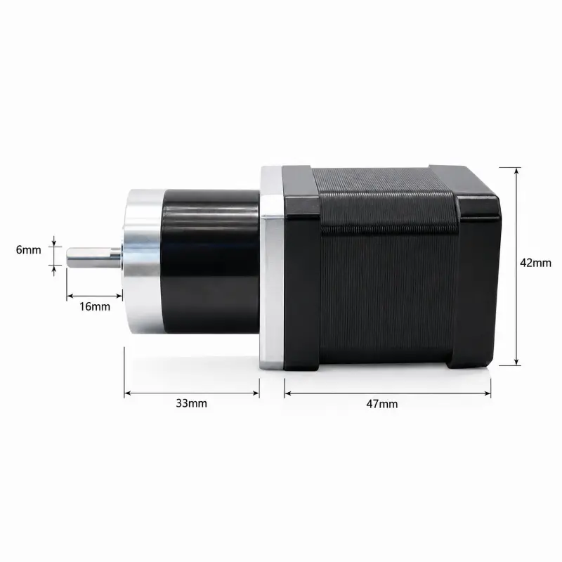
KC-42HYB60 NEMA 17 60mm Mechanical Dimensions
0.9 Degree Step Resolution For Controlled Positioning
A standard 1.8° stepper motor completes 200 full steps per revolution, while a 0.9° motor completes 400 full steps per revolution. The nema 17 0.9 degree stepper therefore provides twice the number of native full-step positions within one mechanical revolution. This characteristic can be useful when the application requires finer incremental motion, smoother low-speed positioning, or more resolution before microstepping is introduced by the driver. The actual positioning accuracy of a nema 17 stepper motor 0.9 degree system still depends on mechanical load, coupling stiffness, driver configuration, current regulation, acceleration, resonance behavior, and the transmission mechanism connected to the shaft.
2 A Winding Configuration And Driver Matching
The KC-42HYB60 is specified as a nema 17 2a motor with a rated current of 2 A per phase, 1.8 Ω phase resistance, and 5.2 mH inductance. These winding values are important when selecting a stepper driver because the driver should regulate phase current rather than relying only on the nominal supply voltage. A compatible driver should provide suitable current adjustment and should be selected with consideration for operating speed, required torque, duty cycle, ambient conditions, and available cooling. Higher supply voltage can improve current rise at increasing step rates when used with a current-controlled driver, but the final electrical configuration should remain within the limits of the selected driver and the thermal capability of the motor installation.
Hybrid Stepper Construction And Load Holding
As a nema 17 hybrid stepper motor, the KC-42HYB60 uses the common hybrid stepper architecture associated with controlled incremental rotation and energized holding capability. Its specified holding torque is 6.7 kg·cm. Holding torque represents static torque under the specified energized condition and should not be interpreted as the available running torque at every operating speed. Dynamic torque generally decreases as step frequency increases, so engineering selection should consider the actual torque-speed requirement rather than holding torque alone. Load inertia, acceleration, lead screw pitch, pulley diameter, gearbox ratio, friction, and safety margin can all influence whether the motor is appropriate for a particular mechanism.
KC-42HYB60 Performance Advantages
Fine Native Step Resolution
The 0.9° full-step angle provides 400 full steps per revolution, supporting controlled incremental positioning where finer native resolution is required.
Defined Holding Capability
The 6.7 kg·cm holding torque specification provides a clear reference point for evaluating static load requirements and comparing related 42 mm frame motors.
Standardized Mounting Interface
The 42.2 mm frame, 31 ± 0.1 mm mounting spacing, four M3 threaded holes, and Ø22 mm front boss support predictable mechanical integration.
Configurable Output Shaft
Available Ø5 mm, Ø6.5 mm, and Ø8 mm shaft diameters can be combined with configurable D-shaft width, output length, and flat length for mechanical adaptation.
Smooth Motion Characteristics
The two-phase hybrid construction and 0.9° step angle support smooth controlled rotation when the motor is paired with a properly configured current-regulated driver.
Series Selection Flexibility
Related body lengths from 24 mm to 68 mm allow engineers to compare winding data, current, torque, shaft length, and installation depth within the same 42 mm frame family.
High Torque NEMA 17 Stepper Motor Integration Considerations
When evaluating a high torque nema 17 stepper motor, holding torque should be considered together with the motor body length, winding characteristics, operating current, speed range, and mechanical transmission. The KC-42HYB60 provides 6.7 kg·cm holding torque from a 60 mm body while using a 0.9° step angle and 2 A rated current. The related KC-42HYB68 provides a higher listed holding torque of 8.7 kg·cm but uses a 1.8° step angle, demonstrating why motor selection should not be based on torque alone.
The 60 mm body is particularly relevant when installation depth allows a longer motor and the application benefits from the corresponding winding and torque characteristics. Designers should confirm available axial space for the motor body, 40 mm shaft, coupling, pulley, lead screw interface, wiring bend radius, and any rear-side connector or cable routing. The 31 ± 0.1 mm mounting hole spacing and four M3 threaded holes should also be incorporated into the mounting plate design with appropriate tolerance control.
For precision positioning equipment, the drivetrain should be evaluated as a complete system. A 0.9° motor can increase native step resolution, but backlash, shaft coupling compliance, lead screw error, belt elasticity, structural deflection, bearing clearance, and control tuning may contribute more positioning error than the nominal motor step angle. For this reason, the motor specification should be coordinated with the mechanical transmission, driver electronics, motion controller, target acceleration, load profile, and required repeatability.