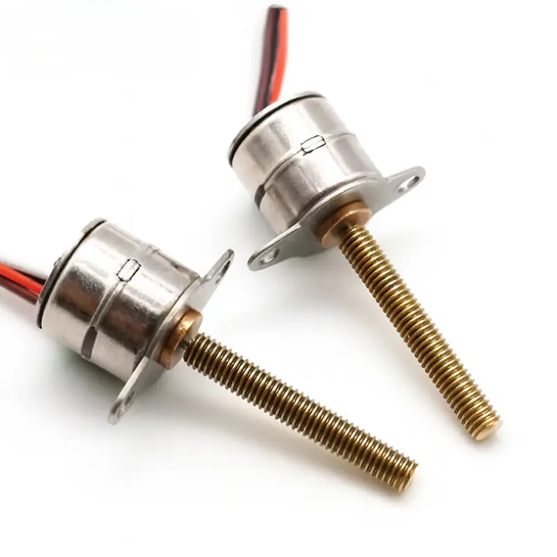
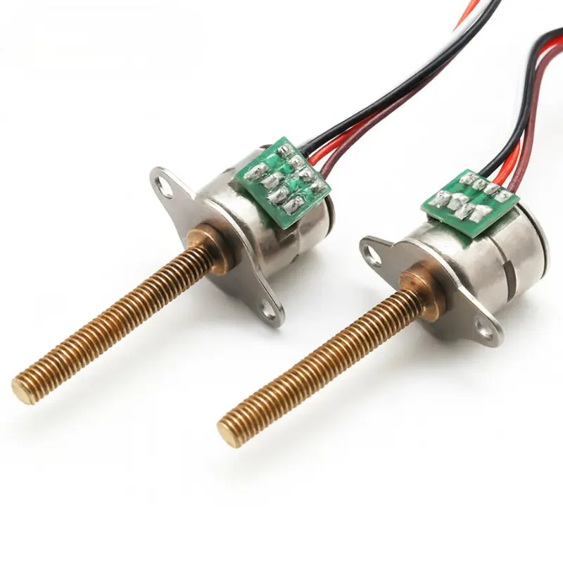
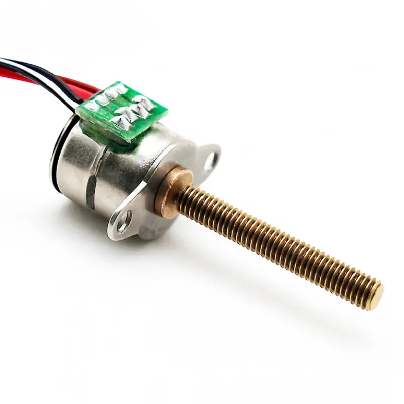
10mm Micro Stepper Motor with Lead Screw 30mm, 5V DC, KC-10BY25
KC-10BY25 Linear Stepper Motor Technical Specifications
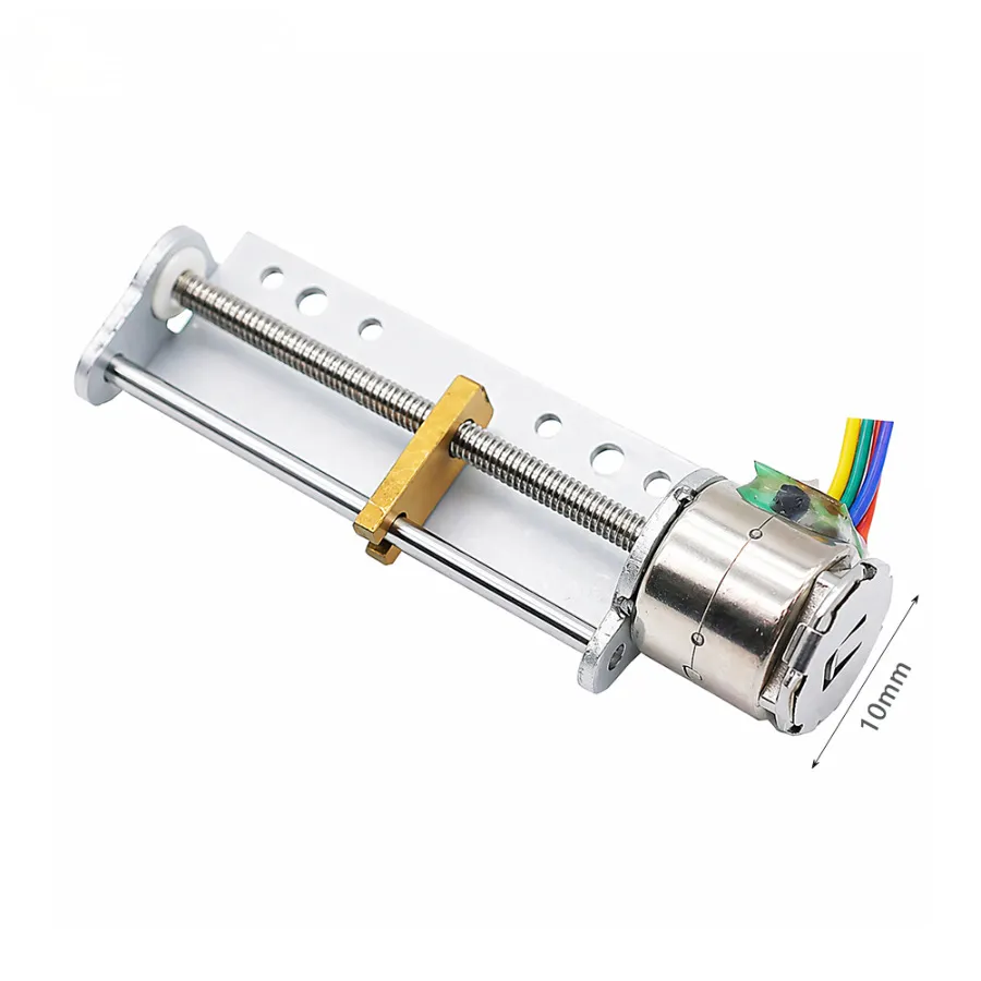
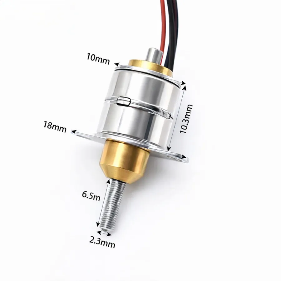
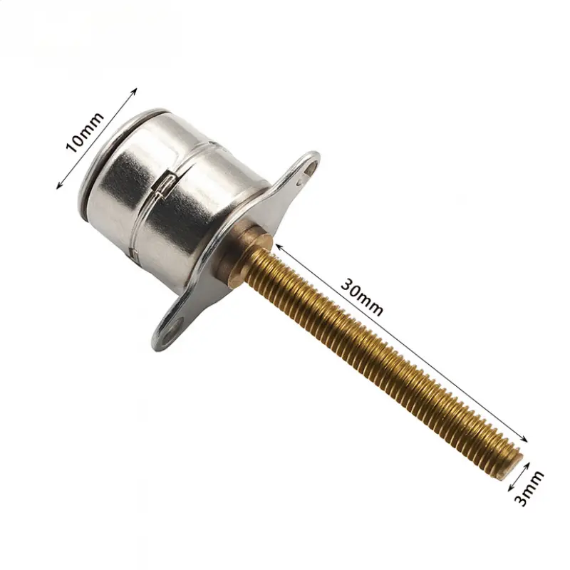
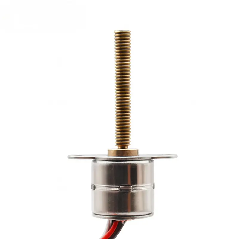
The Kechen Motor KC-10BY25 is a micro stepper motor with lead screw featuring a 10 mm permanent magnet motor body, an M3 × 0.5 external threaded shaft, and a two-hole mounting flange. Its 5 V bipolar configuration is intended for small linear positioning mechanisms where motor dimensions, mounting alignment, and screw-driven motion are key design considerations.
Motor, Lead Screw and Mechanical Specifications
| Parameter | Specification |
|---|---|
| Motor and Electrical Data | |
| Model | KC-10BY25 |
| Brand | Kechen Motor |
| Motor Type | 2-phase permanent magnet stepper motor |
| Configuration | External lead screw with two-hole mounting flange |
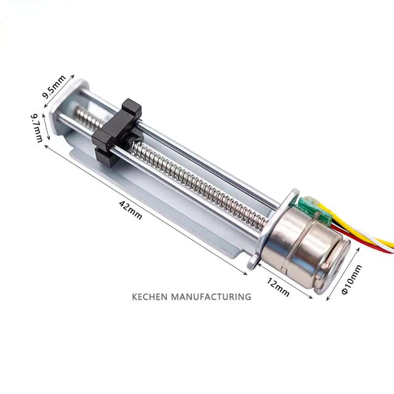
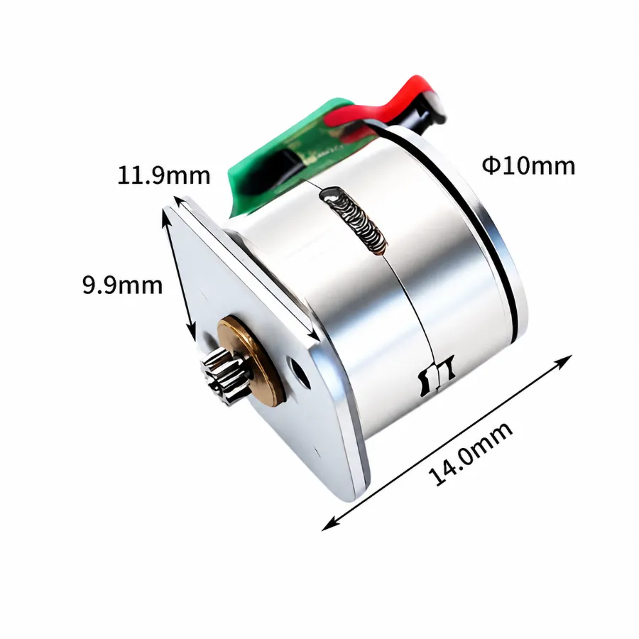
| Motor Diameter | Ø10 mm |
| Motor Body Length | 10.2 ± 0.15 mm |
| Rated Voltage | 5.0 V DC |
| Number of Phases | 2 |
| Step Angle | 18° per step |
| Coil Resistance | 10 Ω ± 10% per phase at 25 °C |
| Drive Mode | Bipolar drive |
| Excitation Method | 2-2 phase excitation |
| Lead Screw Dimensions | |
| Lead Screw Type | External threaded lead screw |
| Lead Screw Diameter | Ø3 mm |
| Thread Specification | M3 × 0.5 |
| Thread Pitch | 0.5 mm |
| Lead Screw Length | 30 ± 0.2 mm |
| Lead Screw Nut Width | 6 ± 0.1 mm |
| Lead Screw Nut Thickness | 3 ± 0.1 mm |
| Mounting and Mechanical Dimensions | |
| Mounting Type | Two-ear mounting flange |
| Mounting Hole Quantity | 2 |
| Mounting Hole Diameter | Ø2.2 mm |
| Mounting Hole Spacing | 14 ± 0.05 mm (center to center) |
| Mounting Ear Radius | 2 × R1.9 mm |
| Flange Center Radius | R3 mm |
| Front Flange Thickness | 0.5 mm |
| Rear Center Pin Diameter | Ø1 mm |
| Rear Boss Diameter | Ø4 mm (upper tolerance 0 mm; lower tolerance −0.05 mm) |
| Wiring and Connector Data | |
| Wire Configuration | 4-wire bipolar |
| Cable Specification | UL1571, 30 AWG |
| Cable Length | 90 ± 5 mm |
| Connector Model | 51021-0400 |
| Connector Pitch | 1.25 mm |
| Connector Positions | 4 |
| Motor-Side Wire Order | White, black, red, brown (top to bottom) |
| Connector-Side Wire Order | Brown, black, white, red (top to bottom) |
Wiring Note: The motor-side and connector-side wire sequences differ in the supplied documentation. Connector pin assignments and motor phase pairs require confirmation before electrical integration.
Performance and Insulation Specifications
| Parameter | Test Value |
|---|---|
| Motion Performance | |
| Pull-Out Thrust | More than 240 g at 800 PPS (drawing reference) |
| Maximum Pull-In Frequency | More than 1,000 PPS |
| Maximum Pull-Out Frequency | More than 1,500 PPS |
| Electrical Insulation and Operating Conditions | |
| Insulation Class | Class E for coils |
| Dielectric Strength | 100 V AC for 1 s |
| Insulation Resistance | 50 MΩ at 500 V DC |
| Operating Temperature | 0 °C to +55 °C |
Performance Note:
The thrust value retains the gram-based notation specified in the engineering drawing. Pull-in frequency describes starting capability, while pull-out frequency describes operation under different test conditions. Actual thrust, starting behavior, and operating frequency depend on the mechanical load, drive circuit, and test conditions.
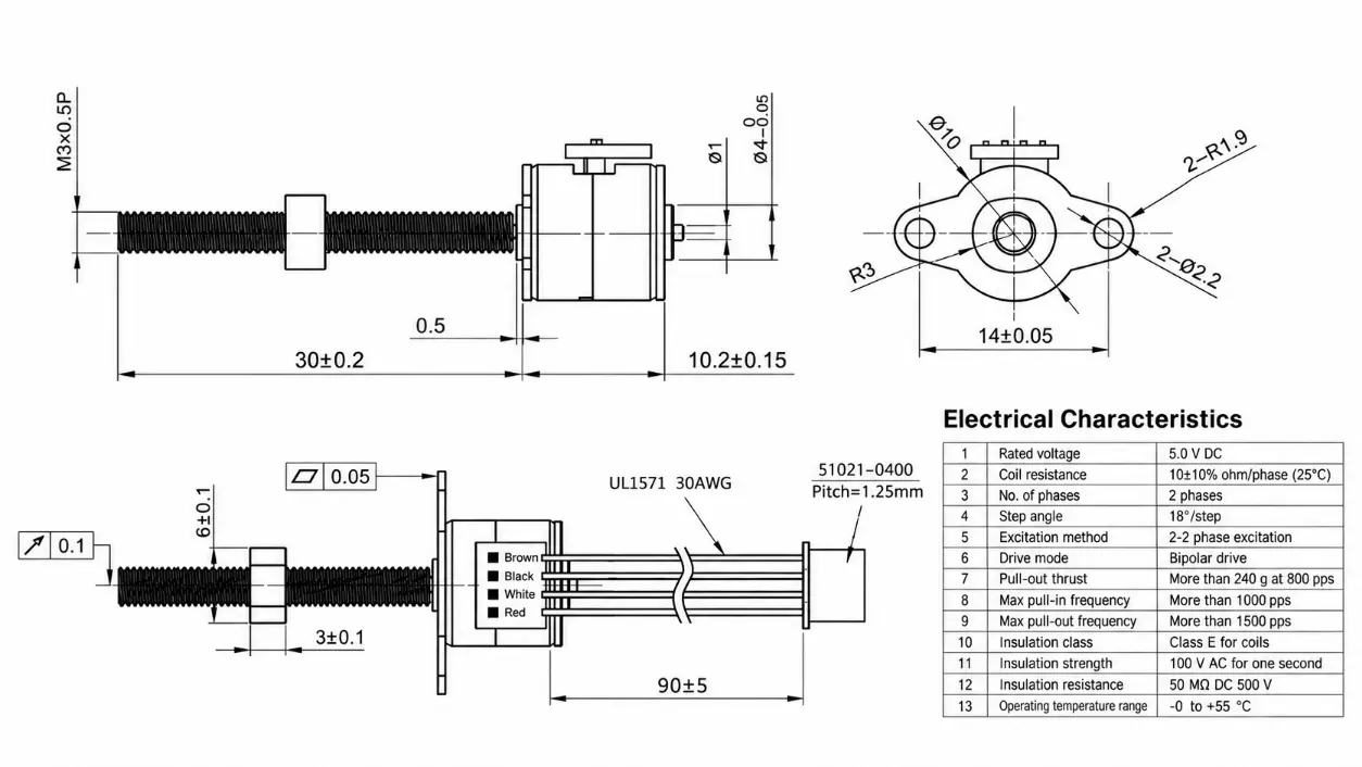
KC-10BY25 Mechanical Dimensions and Lead Screw Drawing
The mechanical drawing provides reference dimensions for the motor housing, mounting flange, threaded shaft, and connector arrangement. These dimensions should be checked against the intended installation space and mating components before design approval.
Technical Advantages
1. Screw-Driven Linear Motion:
The external threaded shaft converts motor rotation into linear displacement when paired with a compatible nut and guided mechanism.
2. Defined Mounting Interface:
The two-hole flange provides a mechanical attachment interface for positioning the motor within space-constrained assemblies.
3. Bipolar Stepper Control:
The four-wire configuration supports operation with a compatible bipolar stepper driver, subject to confirmed phase wiring and drive settings.
4. Engineering Reference Data:
Documented motion and insulation tests provide a basis for initial actuator evaluation before application-specific sample testing.
Integration and Configuration Notes
Lead Screw Travel
The specified screw length does not represent available linear stroke. Usable travel depends on nut engagement, end clearances, and the surrounding mechanical assembly.
Lead Screw Nut
Nut dimensions are included in the technical drawing. Nut supply and compatibility with the final mechanical assembly require confirmation.
Driver and Wiring Validation
The driver selection should account for winding resistance, operating voltage, drive current, and commanded pulse frequency. Verify motor phase connections and connector pin assignments before testing.
Sample Approval
Confirm mechanical fit, screw travel, thrust under load, electrical connections, and operating conditions using approved samples before production integration.
Payment and Shipping
Payment
1. Quotation-Based Terms:
Payment conditions are confirmed through the formal quotation according to the approved motor configuration and order requirements.
2. Sample and Production Orders:
Commercial terms are agreed upon before sample preparation or production processing.
Shipping
1. Shipping Arrangement:
Transportation arrangements are confirmed based on destination, shipment quantity, and project requirements.
2. Delivery Schedule:
Production readiness and estimated dispatch dates are provided after configuration and order details are confirmed.
KC-10BY25 Frequently Asked Questions
Q1. Does the KC-10BY25 Provide a 30 mm Linear Stroke?
A: No. The 30 mm dimension refers to the lead screw length. Actual linear travel depends on the nut position, available thread engagement, and mechanical travel limits.
Q2. Is the KC-10BY25 Compatible With a Bipolar Stepper Driver?
A: The motor uses a two-phase, four-wire bipolar configuration. The selected driver must support the required electrical characteristics, and the winding connections must be verified before operation.
Q3. Is a Lead Screw Nut Included With the Motor?
A: A matching nut is shown in the engineering drawing, but its inclusion in the supplied configuration has not been confirmed. The nut specification and supply requirements should be verified during quotation.
Q4. Can the Published Pull-Out Thrust Be Used as the Continuous Working Load?
A: Not directly. The published value is a reference test result at a specified pulse rate. Continuous working load must be established through testing under the intended drive, motion profile, duty cycle, and mechanical load conditions.
Q5. Can the Lead Screw or Wiring Configuration Be Modified?
A: Alternative screw dimensions, cable lengths, and connector arrangements can be submitted for engineering review. Feasibility and final specifications depend on the requested configuration and sample validation.
Technical Disclaimer:
Specifications are for reference only. Final parameters should be confirmed based on approved samples and project requirements. Mechanical dimensions, wiring assignments, thrust performance, and supplied accessories must be verified against the approved product configuration.