10mm Stepper Motor Linear Slide with Plastic Carriage and Lead Screw 5V DC
10mm Stepper Motor Linear Slide Technical Specifications
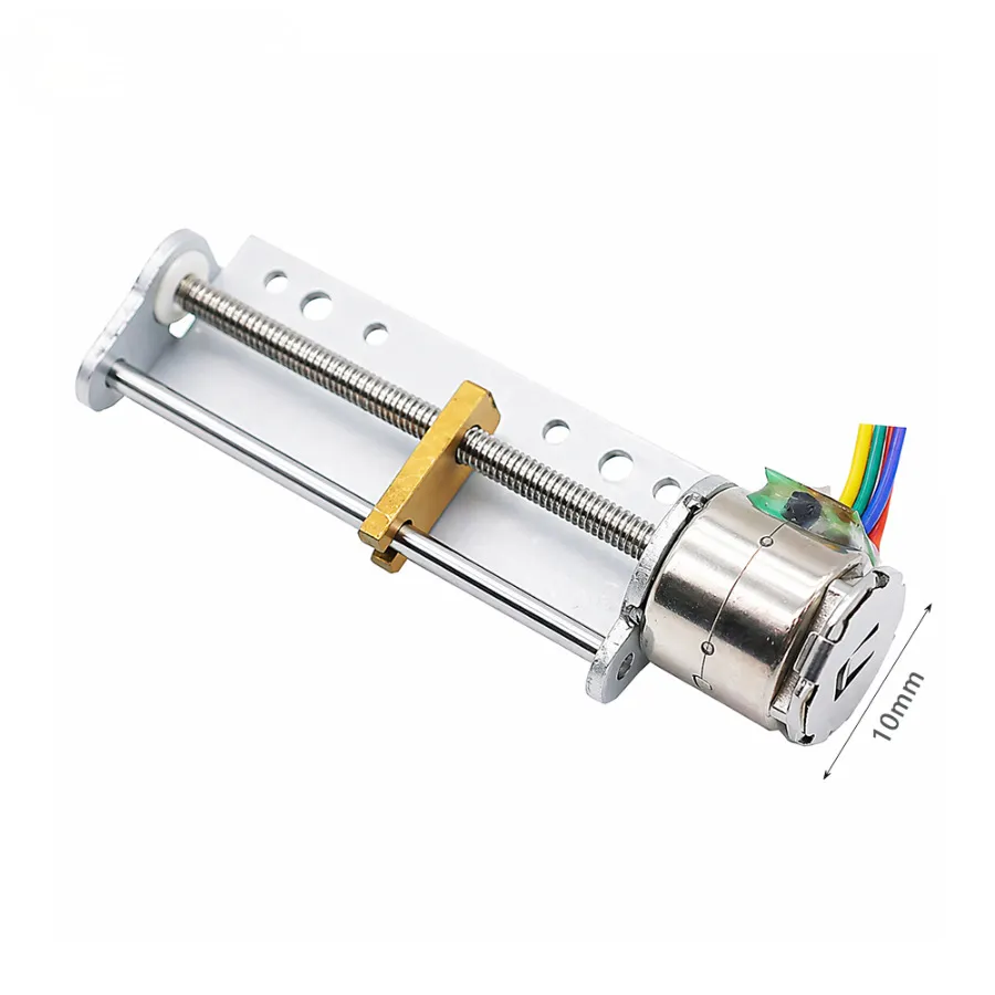
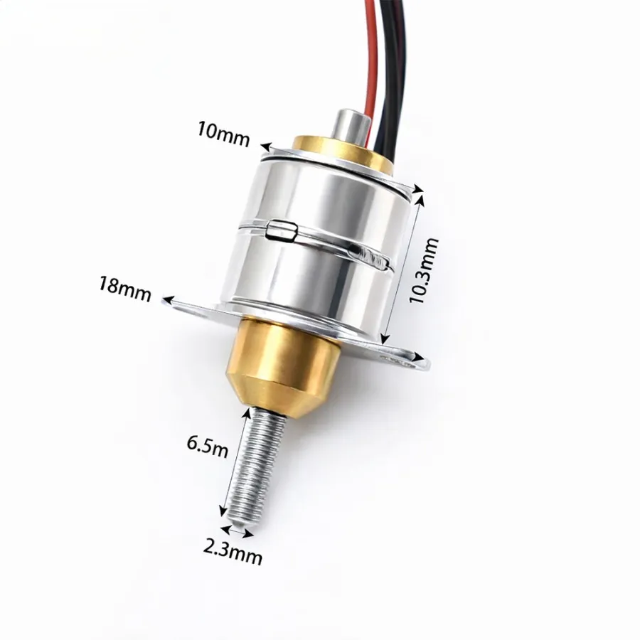
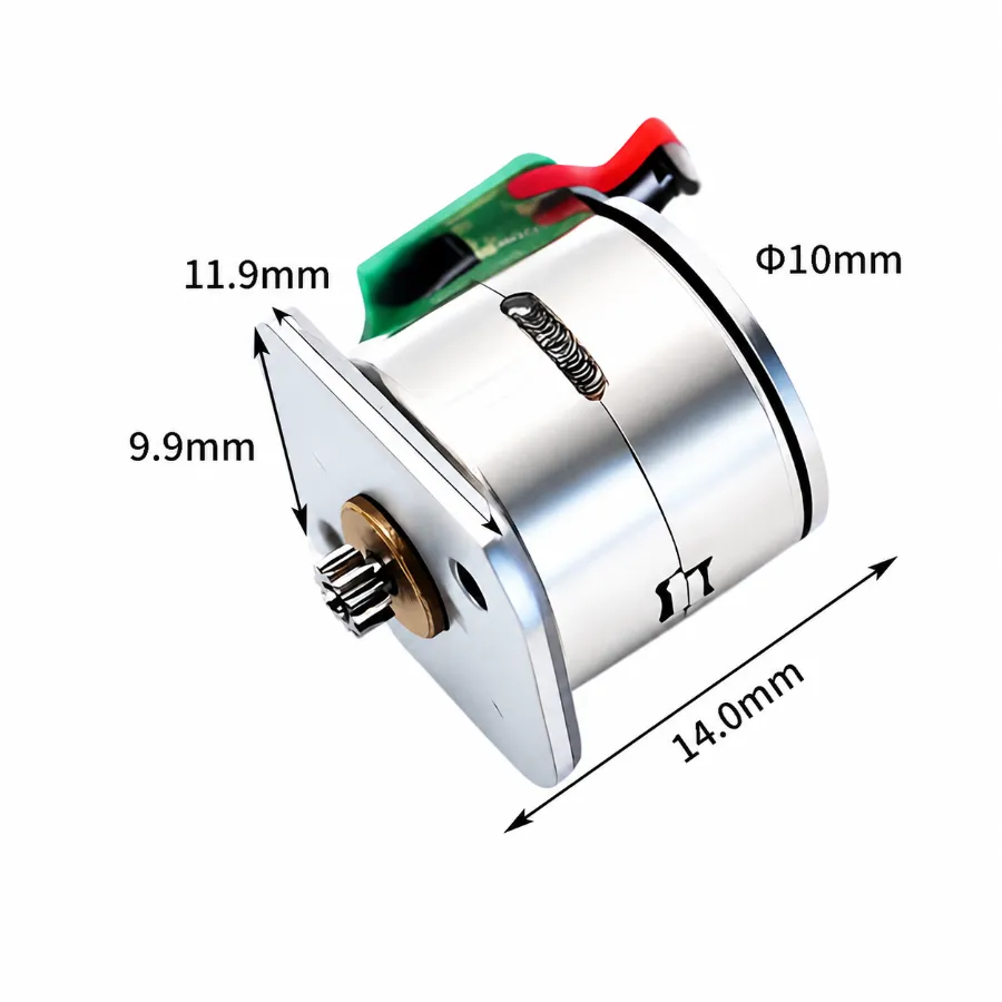
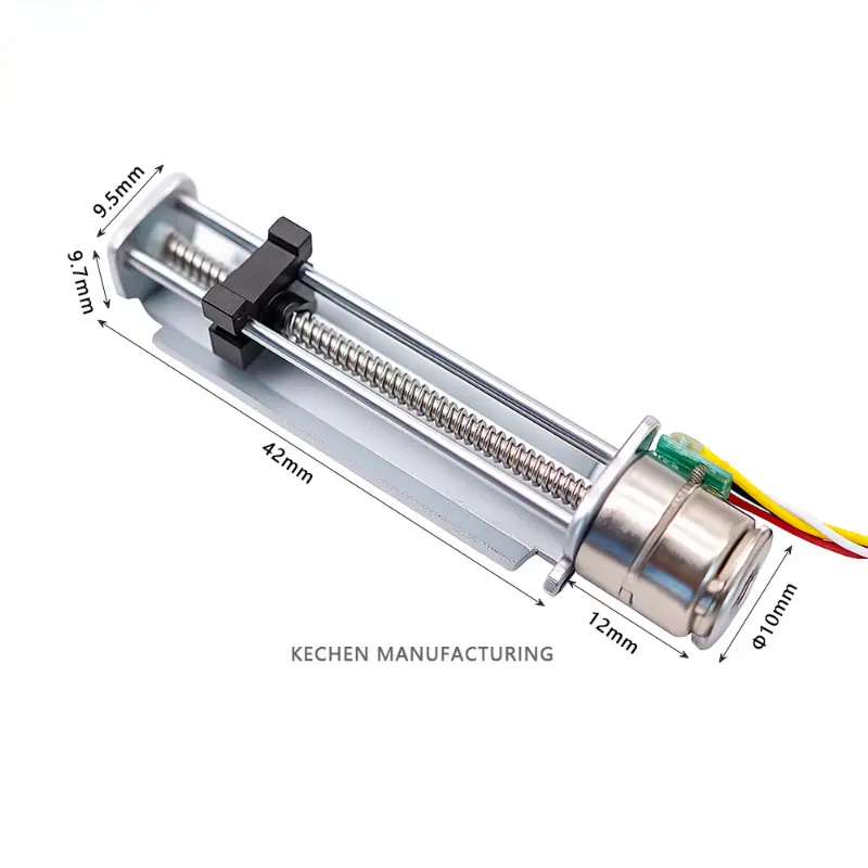
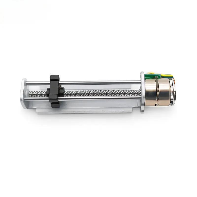
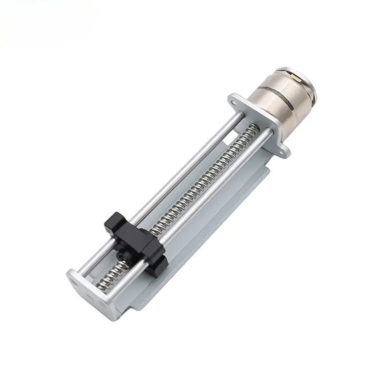
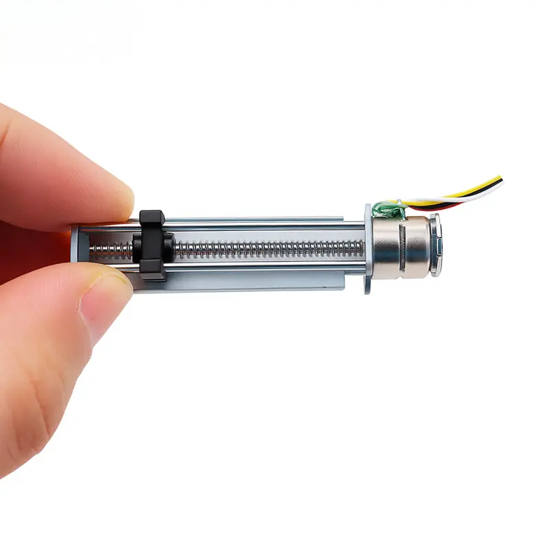
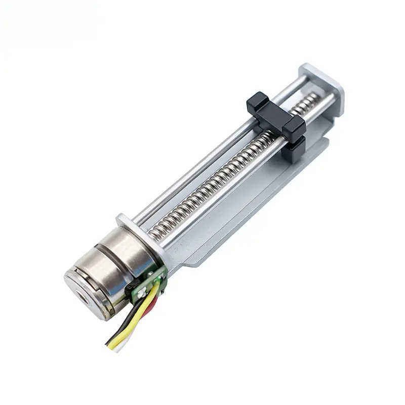
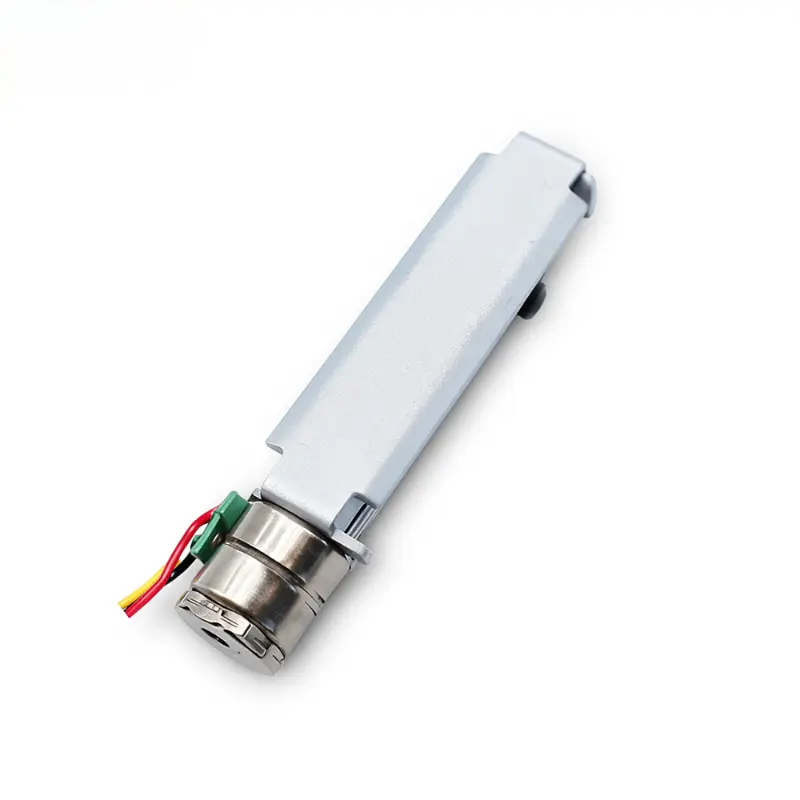
The KC-10BY-42 is a 10mm stepper motor linear slide combining a permanent magnet stepper motor, lead screw transmission, plastic sliding carriage, and metal guide rails. The assembly is designed for electrically controlled linear movement in space-constrained mechanisms. Its rated electrical configuration is 5 V DC, with additional test data available at 3.7 V DC.
KC-10BY-42 Electrical and Mechanical Specifications
Product specifications and engineering drawing dimensions. Dimensional values are in millimeters unless otherwise indicated.
| Parameter | Specification |
|---|---|
| Product Identification | |
| Product Name | 10 mm linear stepper motor with plastic slide |
| Brand | Kechen Motor |
| Slide Model | KC-10BY-42 |
| Motor Drawing Model | KC-10BY25 |
| Product Type | Lead screw linear stepper motor assembly |
| Motor Type | Permanent magnet stepper motor |
| Drive Mechanism | Lead screw with linear sliding carriage |
| Slide Structure | Plastic carriage with metal guide rails |
| Electrical and Drive Specifications | |
| Rated Voltage | 5 V DC |
| Tested Voltages | 3.7 V DC / 5 V DC |
| Step Angle | 18° per step |
| Coil Resistance Options | 10 Ω / 20 Ω / 30 Ω |
| Test Winding Resistance | 20 Ω |
| Drive Configuration | 2-phase, 2-pole |
| Winding Sequence | A+ / A− / B+ / B− |
| Rotation Reference | CW / CCW, viewed from flange side |
| Slide and Motor Dimensions | |
| Nominal Motor Diameter | 10 mm |
| Drawing Motor Diameter | Ø10.2 ± 0.1 mm |
| Motor Body Length | 11 mm max. |
| Linear Section Length | 42 ± 0.3 mm |
| Catalog Total Stroke | 42 mm, usable travel requires confirmation |
| Guide/Base Length | 34 mm |
| Carriage Feature Dimensions | 3 mm / 6 mm |
| Slider/Guide Dimensions | 5.5 mm / 9.5 mm |
| End Section Width | 12 ± 0.15 mm |
| End Feature Dimension | 9.5 mm |
| Side View Height | 9.65 ± 0.15 mm |
| Centerline Offset | 5.4 ± 0.1 mm |
| Mounting Flange Dimensions | |
| Overall Flange Width | 13.25 mm |
| Flange Dimension A | 10.26 ± 0.15 mm |
| Flange Dimension B | 10.65 ± 0.15 mm |
| Lower Flange Feature | 7 mm |
| Flange Angle | 25° |
| Connector and Wiring Specifications | |
| Drawing Connector | SH1.0-4P |
| Terminal Pitch Options | 1.0 mm / 1.25 mm / 1.5 mm |
| Lead Wire Specification | 3302, 30 AWG |
| Lead Wire Length | 25 ± 5 mm |
| Number of Wires | 4 |
| Pin 1 | White – Phase A− |
| Pin 2 | Yellow – Phase A+ |
| Pin 3 | Black – Phase B− |
| Pin 4 | Red – Phase B+ |
| Reference Performance Information | |
| Unverified Catalog Thrust Entry | 190 g·cm, as printed in the source; the unit denotes torque rather than linear thrust and requires verification |
Engineering note: The product information identifies the slide as KC-10BY-42, while the dimensional drawing uses KC-10BY25. Assembly correspondence and usable carriage travel should be verified against the approved drawing and sample.
KC-10BY-42 Linear Thrust Performance Test
The following measurements were recorded with a 20 Ω winding during upward and downward linear motion testing. Current and thrust depend on the applied voltage and pulse frequency. These results should not be treated as universal limits for other winding configurations.
| Voltage | Pulse Rate | Current | Thrust |
|---|---|---|---|
| 3.7 V DC Test Conditions | |||
| 3.7 V | 100 PPS | 320 mA | 155 gf |
| 3.7 V | 200 PPS | 300 mA | 130 gf |
| 3.7 V | 400 PPS | 293 mA | 115 gf |
| 3.7 V | 600 PPS | 280 mA | 100 gf |
| 3.7 V | 800 PPS | 240 mA | 85 gf |
| 5 V DC Test Conditions | |||
| 5 V | 100 PPS | 425 mA | 220 gf |
| 5 V | 200 PPS | 407 mA | 205 gf |
| 5 V | 400 PPS | 370 mA | 175 gf |
| 5 V | 600 PPS | 350 mA | 150 gf |
| 5 V | 800 PPS | 326 mA | 130 gf |
Performance Interpretation:
The highest recorded thrust in the supplied test series is 220 gf at 5 V DC and 100 PPS. The measured thrust decreases as the test pulse rate increases. Selection should therefore be based on the intended operating frequency and load rather than a single thrust measurement.
10mm Stepper Motor Linear Slide Dimensions and Mechanical Drawing
KC-10BY25 drawing reference | Lead screw drive, sliding carriage, and mounting dimensions
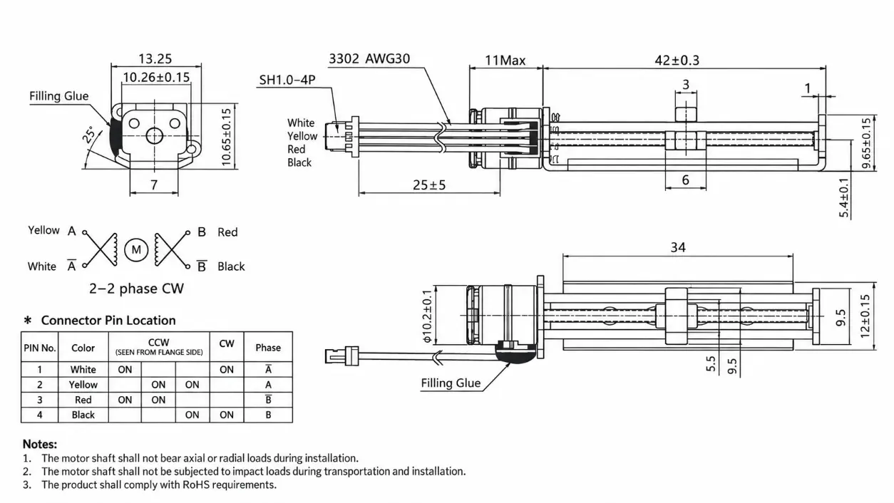
The drawing provides the motor housing and slide mounting geometry for mechanical integration. The specified linear-section dimension does not independently establish the available carriage travel. Verify travel limits, carriage clearance, and assembly configuration before finalizing the installation.
KC-10BY-42 Performance and Design Advantages
Integrated Lead Screw and Guided Carriage
The motor, lead screw, plastic slider, and metal guide rails form a single linear motion assembly, reducing the need to design separate carriage guidance around a bare lead screw motor.
Measured Thrust Across Different Pulse Rates
Available thrust measurements allow engineers to evaluate the relationship between pulse frequency and linear load capacity within the documented test conditions.
Defined Mechanical Interface
The supplied drawing identifies the motor envelope, mounting flange, guide dimensions, and wiring orientation for early-stage equipment layout and fit assessment.
Electrical Configuration Options
Multiple winding resistance and connector pitch options support application-specific electrical interfaces. Final combinations and performance require confirmation through approved samples.
Applications and OEM Configuration
This micro linear stepper motor assembly can be evaluated for miniature positioning mechanisms, optical adjustment equipment, instrument sliders, and small electromechanical modules where guided linear travel is required.
For use as a stepper motor linear actuator, the required load, usable stroke, movement frequency, and installation orientation should be established before selecting the winding and connector configuration. OEM inquiries should include the expected duty cycle, available mounting space, and project quantity.
Payment and Order Requirements
- Payment Terms:
Payment arrangements are confirmed in the commercial quotation and agreed before order processing. - Configuration Confirmation:
Motor winding, connector, slide dimensions, and required travel should be confirmed before finalizing the order. - OEM Project Documentation:
Approved drawings and sample requirements are used to establish the final supply configuration.
Shipping and Delivery
- Shipping Method:
Freight arrangements are confirmed according to the destination, shipment volume, and agreed trade terms. - Delivery Schedule:
The production and dispatch schedule depends on the approved motor configuration and order quantity. - Export Packaging:
Packaging requirements are reviewed according to the product assembly and transportation conditions.
KC-10BY-42 Frequently Asked Questions
Q1: Does the 42 mm Dimension Represent the Actual Travel?
A: Not yet confirmed. The product information lists a 42 mm total stroke, while the drawing identifies a 42 ± 0.3 mm linear-section dimension. The usable stroke must be verified with the final assembly.
Q2: What Thrust Can the 5 V Linear Slide Deliver?
A: The supplied test data records 220 gf at 100 PPS using the 20 Ω winding at 5 V DC. This is a measured operating point rather than a verified maximum thrust for every configuration.
Q3: Can the KC-10BY-42 Operate at 3.7 V DC?
A: Yes, the supplied performance data includes 3.7 V DC testing with a 20 Ω winding. The required thrust and operating frequency should be checked against the corresponding test results.
Q4: Can the Connector and Winding Resistance Be Selected?
A: The product information lists several winding resistance and terminal pitch options. The engineering drawing specifies an SH1.0-4P connector. Availability of a particular combination requires confirmation.
Q5: Is This Slide the Same as a Bare Lead Screw Stepper Motor?
A: No. The KC-10BY-42 includes a plastic carriage and metal guide rails in addition to the lead screw drive. A bare lead screw stepper motor does not necessarily include these guidance components.
Q6: Why Are KC-10BY-42 and KC-10BY25 Both Listed?
A: KC-10BY-42 identifies the slide in the product specifications, while KC-10BY25 appears on the motor engineering drawing. The exact relationship between these designations should be confirmed before approving the assembly drawing for production.
Related Motor Specifications
Specifications are for reference only. Final electrical parameters, dimensional compatibility, usable travel, and thrust performance should be confirmed based on approved samples and project requirements.