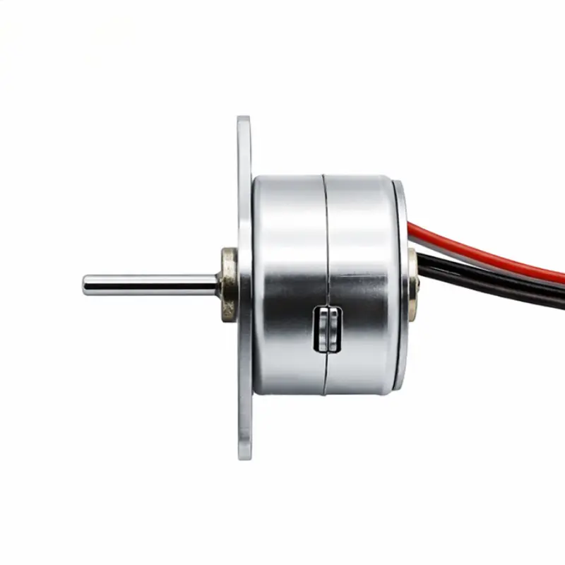
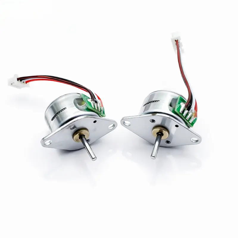
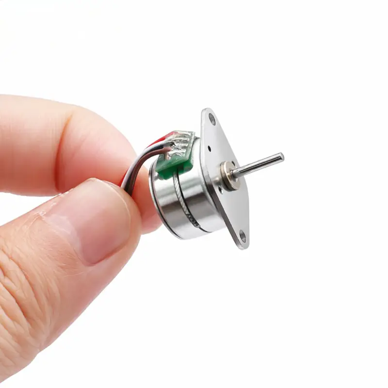
15mm Miniature Stepper Motor Series, 5V/12V 18° Step, 2-Phase 15BY
15mm Miniature Stepper Motor Technical Specifications
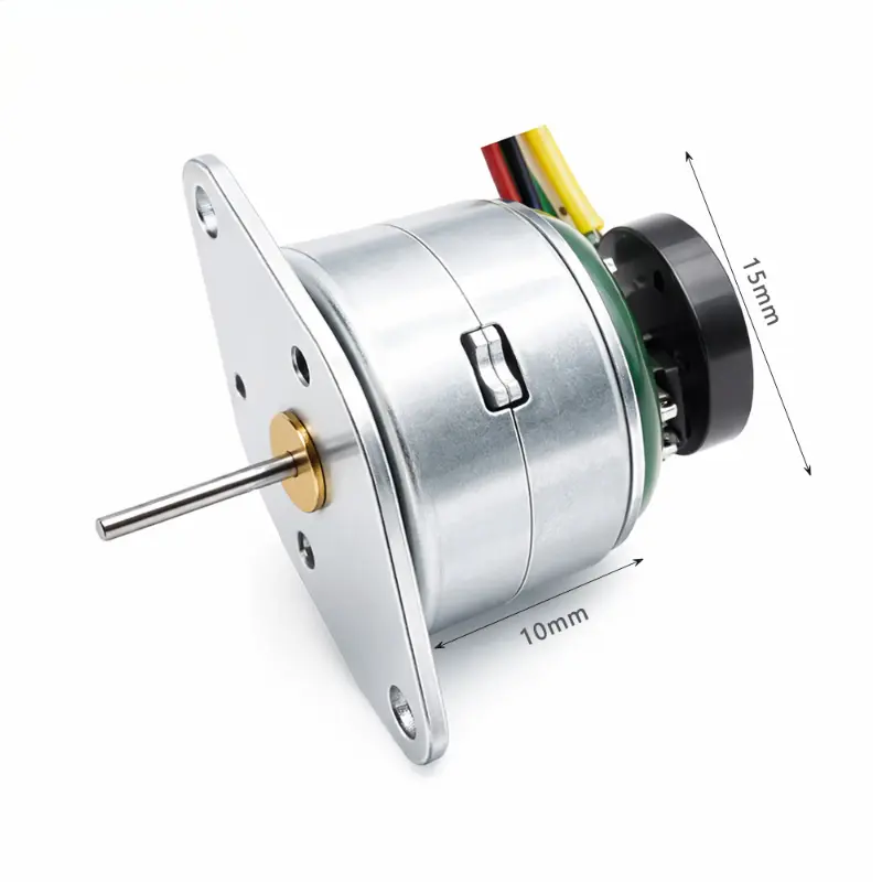
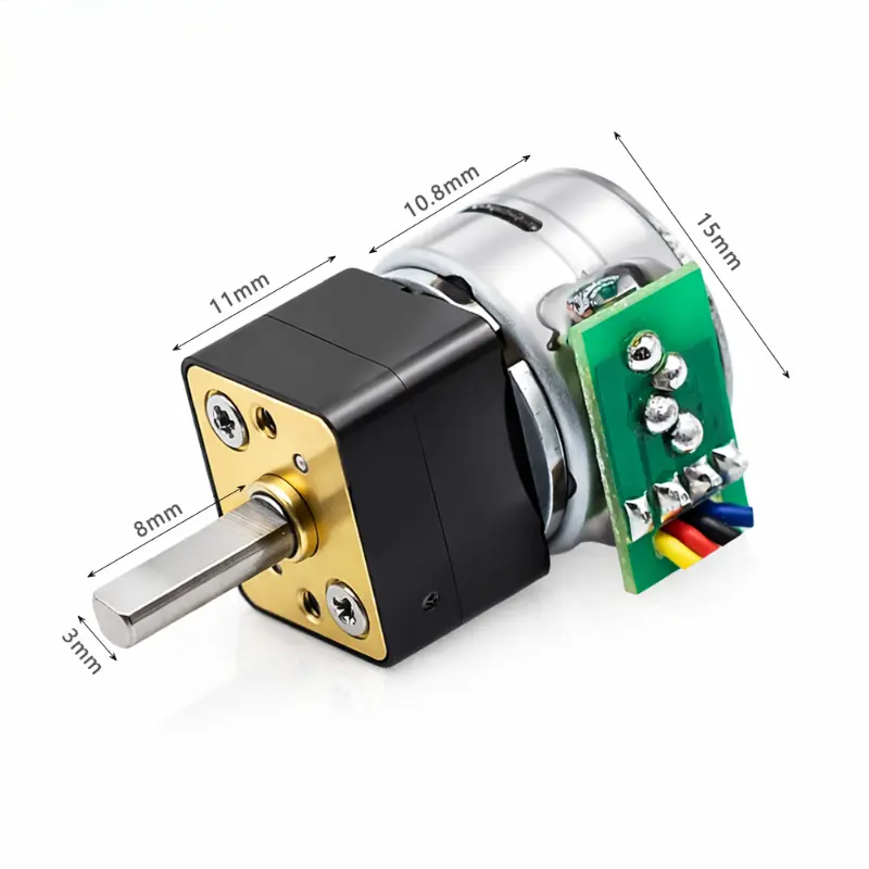
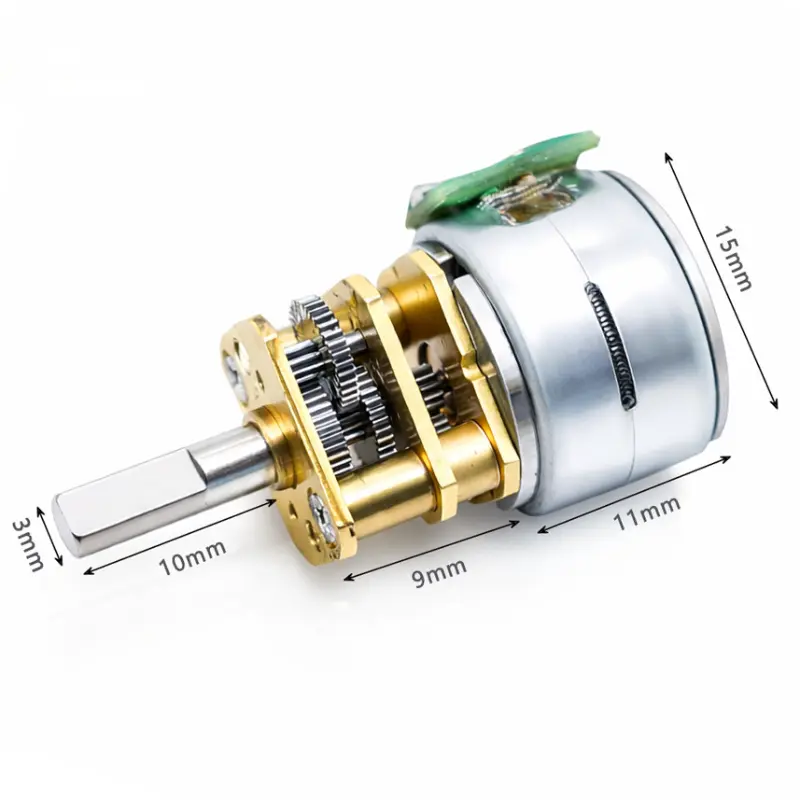
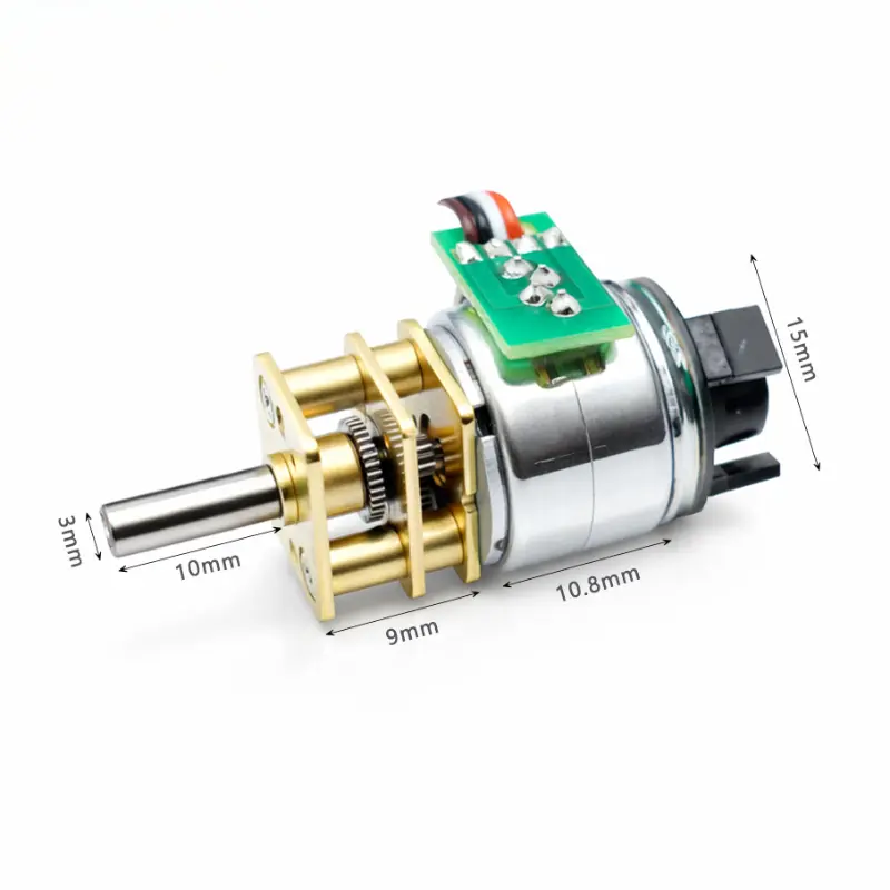
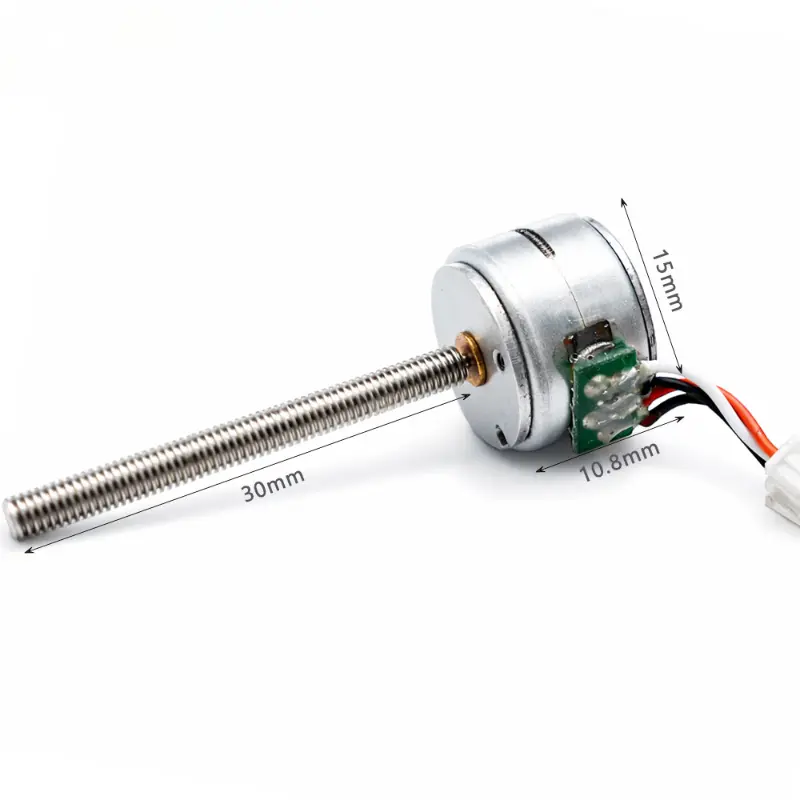
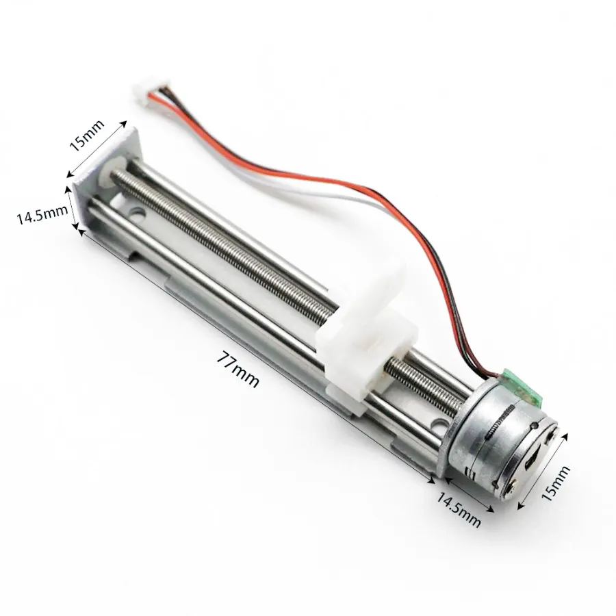
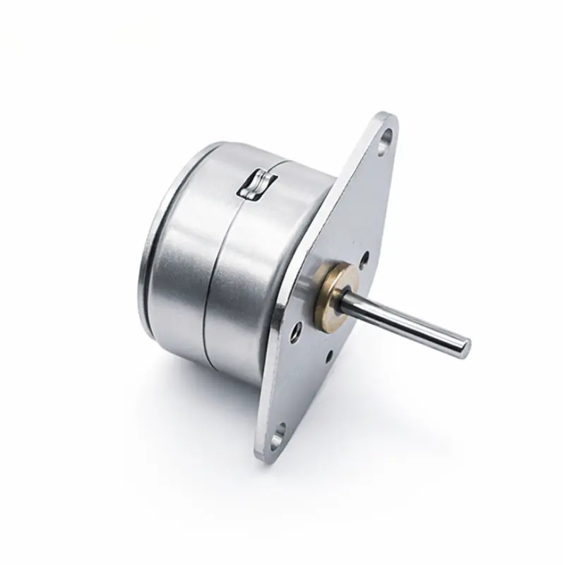
The 15mm miniature stepper motor 15BY series is a 2-phase permanent-magnet stepping motor platform for space-limited positioning mechanisms. The series includes 5 V and 12 V winding options with an 18° step angle, allowing engineers to select the electrical configuration according to the available drive voltage, phase current and required holding torque.
Series Specifications
| Parameter | Specification |
|---|---|
| Product Series | 15BY |
| Motor Type | Stepper motor |
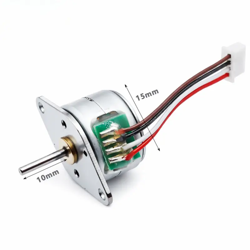
| Marked Motor Dimension | 15 mm |
| Step Angle | 18° |
| Excitation Mode | 2-2 phase |
| Insulation Resistance | ≥ 50 MΩ at 300 V DC |
| Noise | ≤ 50 dB(A) |
| Working Temperature | −10 °C to 50 °C |
| Motor Length | 17.2 mm |
| Shaft Extension Shown | 10 mm |
| Torque Test Condition | At 800 PPS |
15BY Model Electrical And Torque Data
Torque values are based on the stated 800 PPS test condition.
| Model | Voltage | Resistance / Phase | Current | Detent Torque | Holding Torque | Step Angle | Excitation |
|---|---|---|---|---|---|---|---|
| KC-15BY2510-N1 | 5 V DC | 10 Ω | 400 mA | 8 gf·cm | 45 gf·cm | 18° | 2-2 phase |
| KC-15BY2520-N1 | 5 V DC | 20 Ω | 210 mA | 8 gf·cm | 40 gf·cm | 18° | 2-2 phase |
| KC-15BY2540-N1 | 12 V DC | 40 Ω | 300 mA | 8 gf·cm | 55 gf·cm | 18° | 2-2 phase |
Engineering Advantages
- The 15 mm motor format supports integration where available actuator diameter is tightly constrained.
- Three winding configurations allow electrical selection between 5 V and 12 V systems without changing the 15BY product family.
- An 18° mechanical step angle provides 20 full steps per revolution before any drive-side subdivision strategy is considered.
- Model-specific resistance and phase-current values allow the driver circuit to be matched to the selected winding rather than treating the series as one electrical load.
- Holding torque ranges from 40 to 55 gf·cm across the listed models, allowing model selection to account for static load requirements.
- The defined lead colors, connector and mounting dimensions support mechanical and wiring review before prototype integration.
KC-15BY25-160 Mechanical Dimensions And Wiring
Reference dimensions for mechanical integration and lead connection. Dimensions should be confirmed against the approved project drawing and sample.
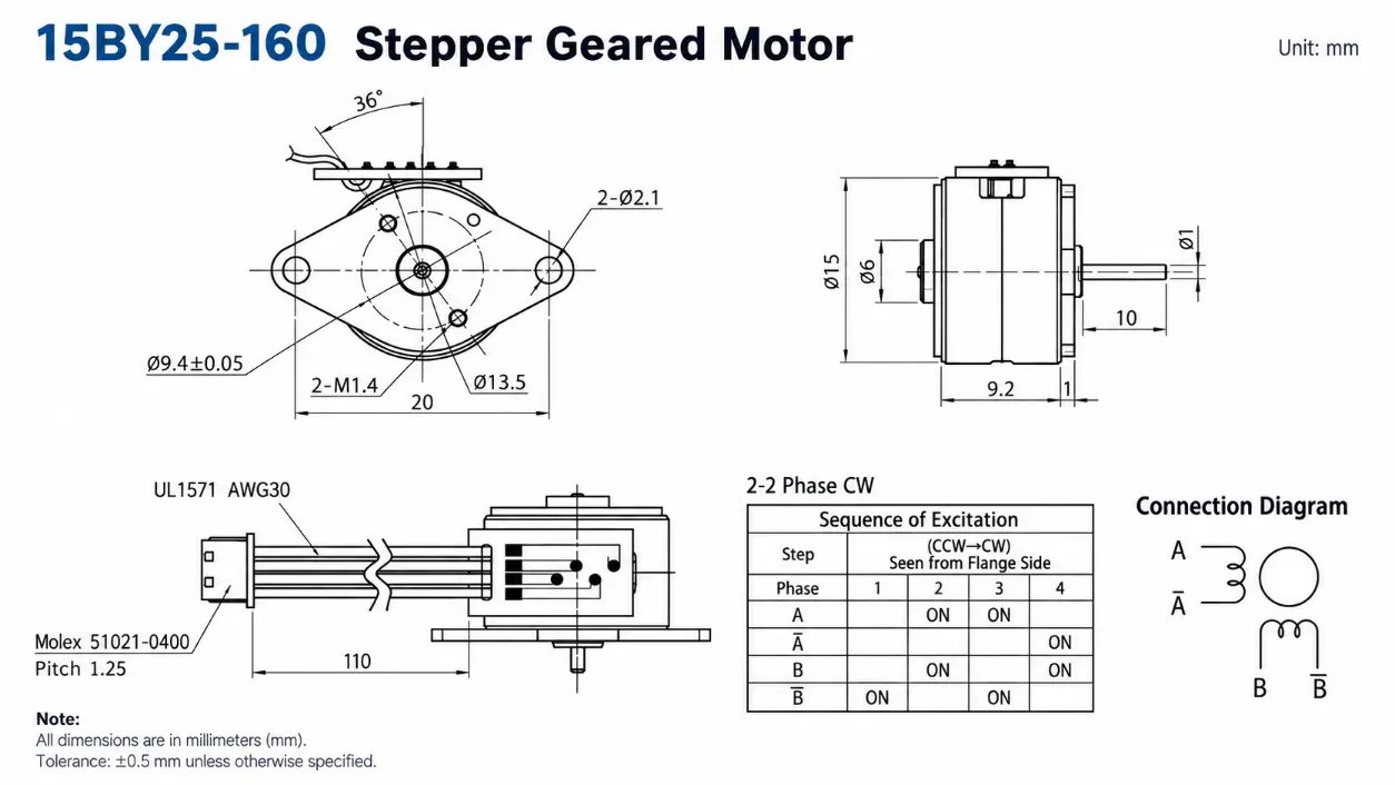
| Drawing Parameter | Specification |
|---|---|
| Drawing Model | KC-15BY25-160 |
| Motor Diameter | Ø15 mm |
| Shaft Diameter | Ø1 mm |
| Rear Boss Diameter | Ø5 mm |
| Motor Body Length | 9.2 mm |
| Front Plate Thickness | 1 mm |
| Mounting Width | 20 mm |
| Mounting Holes | 2 × Ø2.1 mm |
| Threaded Holes | 2 × M1.4 |
| Drawing Diameter | Ø9.4 ± 0.05 mm |
| Drawing Diameter | Ø13.5 mm |
| Lead Exit Angle | 36° |
| Lead Wire Length | 110 mm |
| Lead Wire Specification | UL1571 AWG30 |
| Connector | MOLEX 51021-0400 |
| Connector Pitch | 1.25 mm |
Wiring And Rotation Reference
A: Black
B̅: White
B: Red
Rotation reference: CCW → CW
Viewing direction: Flange side
Model Selection Notes
5 V Configuration
KC-15BY2510-N1 and KC-15BY2520-N1 are the listed 5 V DC winding options. Their different phase resistance and current values should be considered when selecting the driver and available current capacity.
12 V Configuration
KC-15BY2540-N1 is the listed 12 V stepper motor configuration and provides the highest stated holding torque among the three models in this series data.
Mechanical Integration
Use the KC-15BY25-160 drawing to verify the shaft, mounting holes, lead exit position and connector clearance before fixing the surrounding mechanism.
Payment
Shipping
15mm Miniature Stepper Motor FAQ
Which 15BY Model Operates At 12 V DC?
KC-15BY2540-N1 is the listed 12 V DC model. It uses a 40 Ω phase resistance, 300 mA current and an 18° step angle.
Which Models Are Suitable For A 5 V DC Supply?
KC-15BY2510-N1 and KC-15BY2520-N1 are the listed 5 V DC configurations. Their phase current and resistance differ, so the driver should be selected for the specific winding.
Is This A Geared Stepper Motor?
No. The listed 15BY product is a single stepper motor. Gearbox specifications and gear ratios are not part of this product data.
What Does The 18° Step Angle Mean?
An 18° step angle corresponds to 20 full mechanical steps per revolution. Actual motion behavior also depends on the excitation sequence, driver and applied load.
What Is The Torque Test Reference For These Models?
The supplied series data specifies a torque test condition of 800 PPS. Application torque should still be validated under the actual driver, load and operating conditions.
Should The Drawing Be Used As The Final Production Standard?
The drawing is suitable for initial engineering review. Final dimensions, wiring and project-specific requirements should be confirmed against the approved sample and production drawing.