

Micro Motor Blogs
Industrial-Grade 555 DC Motor Tuning: Optimizing Efficiency for Continuous Duty Equipment
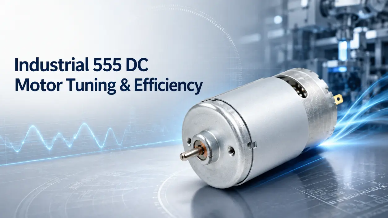
The 555 dc motor series (frame diameter approx. 36 mm, length 50–57 mm) is widely used in power tools, robotics, and light industrial equipment. In continuous-duty scenarios—such as small conveyors, sorting arms, or fluid pumps—sustained operation demands careful attention to thermal limits, voltage regulation, and mechanical load matching. Without proper selection and tuning, brush wear accelerates, winding temperatures rise, and unplanned downtime becomes likely.
Core Electrical and Mechanical Parameters
Reliable system design starts with the actual 555 dc motor specifications provided by the manufacturer. Key parameters include operating voltage range, continuous torque rating, no‑load speed, and current draw at rated load. These values vary significantly across sub‑models (e.g., RS‑555, RH‑555, or variants with different windings). For example, a typical RS‑555 motor at 12 V may deliver a continuous torque between 230 and 290 g‑cm, with no‑load speeds ranging from 4,800 to 7,800 RPM depending on the winding design. Some 24‑V versions can exceed 9,000 RPM. Therefore, quoting a single “standard” value for torque or speed is misleading.
The table below contrasts generic typical values (not universal) against more application‑aligned targets. Always consult the specific datasheet for the exact 555 dc motor you intend to use.
| Parameter | Typical Range (Off‑the‑shelf) | Application‑Matched Selection |
|---|---|---|
| Operating Voltage | 6–24 V DC (model dependent) | Match nominal voltage to power supply |
| Continuous Torque | 200–300 g‑cm (at rated V) | Select model with ≥ required load torque |
| No‑Load Speed | 4,000–16,000 RPM (wide variation) | Choose speed based on reduction ratio |
| Brush Life Expectancy | 500–1,500 hours (depending on load) | Extend with proper filtering and cooling |
Power Regulation and Thermal Management
For a 555 dc motor (or any variant) operating in long cycles, clean power delivery is essential. Unfiltered or unregulated voltage introduces current ripple that accelerates commutator wear. Pulse Width Modulation (PWM) at switching frequencies above the audible range (typically > 20 kHz) helps reduce audible noise and smooths current delivery, which in turn lowers iron losses in the rotor core.
Thermal management directly affects winding insulation life. Under continuous current, resistive heating raises internal temperatures. Placing filtering capacitors directly across the motor terminals can suppress arcing at the brushes. Additionally, providing chassis ventilation or using thermally conductive mounting plates helps dissipate heat and prevents solder‑joint fatigue or insulation breakdown.
Mechanical Adaptation – Gear Motors and Load Coupling
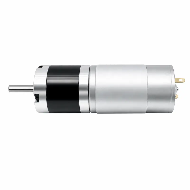
When higher torque is required than an open‑shaft motor can safely provide, a 555 dc motor with a gearhead (often called a 555 gear motor or 555 dc gear motor) offers a practical solution. These units incorporate spur or planetary gearheads that trade output speed for increased torque. When integrating such a gear motor, engineers must verify that the gearbox output shaft can handle the radial and axial loads of the driven mechanism, and that the reduction ratio is calculated to keep the motor operating near its optimal efficiency point.
Mechanical alignment between the motor housing and the load is equally critical. Misalignment introduces parasitic friction, raises current draw, and accelerates bearing and gear wear. Using rigid mounting brackets combined with flexible shaft couplings can accommodate minor structural shifts, reduce backlash, and ensure smoother power transmission over the equipment’s lifetime.
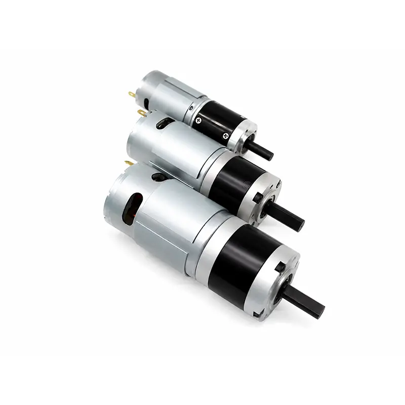
555 12V DC Motor with Planetary Gearbox (36mm)
High-torque planetary gear motor, ideal for robotics and conveyor applications requiring low-speed high-force output.
555 Gear Motor 24V 76RPM Planetary KC-GMP36-555
Efficient 24V gear motor with 76 RPM output, built for long-duty cycles and precise speed control.
Preventive Maintenance for Continuous Operation
Routine inspection is necessary to sustain predictable performance. Technicians should periodically check for abnormal temperature rise, unusual bearing noise, and brush/commutator condition. Darkened commutator segments or uneven carbon dust accumulation often indicate excessive sparking, which may require adjusting the PWM duty cycle, reducing load, or replacing brushes before a full failure occurs.
Conclusion
Effective deployment of a 555 dc motor in continuous‑duty equipment depends on matching the selected model to the actual load profile, voltage supply, and thermal environment. Since specifications vary widely among sub‑models, engineers should always reference the manufacturer’s datasheet rather than relying on generic “standard” numbers. Proper PWM filtering, adequate cooling, and correct mechanical alignment are proven practices that extend service life and reduce downtime.
Frequently Asked Questions
This depends entirely on the specific motor model. Some 555‑series motors are designed for a wide voltage range (e.g., 9–30 V) and can safely run at 24 V. Others are wound exclusively for 12 V, and applying 24 V will exceed the insulation rating and cause rapid overheating even with forced air. Always check the datasheet for the rated voltage range; do not assume that cooling alone permits over‑voltage operation.
Low PWM frequencies (e.g., < 1 kHz) produce higher current ripple, which increases eddy‑current losses in the iron core and generates audible noise. Over time, this ripple also stresses the commutator and brushes, reducing their lifespan. Using a switching frequency above 20 kHz smooths the current waveform, reduces thermal stress, and generally extends brush and commutator life, provided the motor’s inductance is compatible with that frequency.