

Micro Motor Blogs
How to Choose 12V DC Electric Motors Without Costly Sizing Mistakes
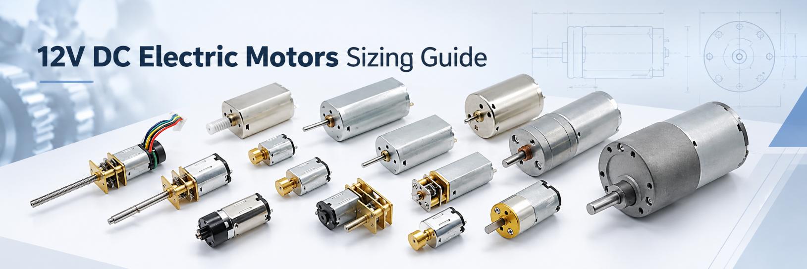
12v dc electric motors can have very different frame sizes, winding designs, speeds, torque and current even when they use the same nominal supply voltage. For an engineer or purchasing team, the 12V label is therefore only an electrical starting point, not a complete motor specification. A comparison of 12V DC electric motors that ignores loaded speed, torque, current and mechanical fit can lead to failed startup, excessive temperature rise or a shaft that does not match the driven part. This article focuses on small and miniature brushed motors used in OEM equipment, including N10, N20, 030, 050, 130, 180, 370 and 555 motor types. Each candidate should be checked by model and winding rather than by motor type alone.
Why 12V DC Electric Motors With the Same Voltage Can Perform Differently
12V DC electric motors may share the same nominal voltage while using different winding resistance, wire diameter, turn count, magnet systems and armature designs. Those differences change the relationship between speed, torque and current. At the same applied voltage and under comparable operating conditions, a lower winding resistance can result in higher current, but resistance alone still does not define the final operating point.
A winding intended for higher shaft speed can behave very differently from a winding intended for lower speed and a different load range. In an actual mechanism, the mismatch may appear as slow acceleration, current above the driver limit, unexpected temperature rise or a loaded speed below the design target.
Winding Design Changes Speed, Torque and Current
When replacing a 12 volt dc electric motor, compare the original duty point rather than matching only the 12V label. Review no-load speed, loaded speed, torque, current, duty cycle and the thermal conditions of the actual assembly. 12V DC electric motors that look similar from the outside can still require different power supplies, controllers or gear ratios because the winding is different.
How Motor Size Changes the Use of 12V DC Electric Motors
Motor frame size affects the physical space available for the magnetic circuit, winding, rotor and thermal path, but actual torque, speed and current still depend on the specific motor design and winding. A larger frame may provide more design capacity for torque and heat dissipation, yet frame size alone does not define operating performance. For 12V DC electric motors, the required duty point still has to be checked against the selected winding and mechanical envelope.
For a small 12v motor, diameter and body length may be fixed by the equipment enclosure before torque calculations are complete. N10, N20, 030 and 050 motors occupy a different mechanical range from 130, 180, 370 and 555 motors, but the motor type alone should not be used to predict current or torque. A larger motor can add mass and installation requirements, while current demand still depends on winding design and operating load.
Small Motor Size vs Available Torque
When sourcing small electric motors 12v systems, compare body dimensions, shaft geometry, loaded speed, required torque, current and duty cycle as one set of constraints. A mechanism with frequent starts may require more operating margin than one with a light continuous load. The useful engineering question is not which motor type is larger, but which motor can operate at the required duty point without exceeding electrical, thermal or mechanical limits.
Comparing Small 12V DC Motor Types and Configurations
12v dc electric motors should be compared by both motor type and drive configuration. A bare motor and a geared motor may use the same nominal supply voltage, but their published speed and torque values describe different mechanical points. Bare-motor specifications refer to the motor shaft, while gearmotor specifications refer to the gearbox output shaft. The verified examples below show why those values should not be mixed without identifying the configuration.
| Motor Type | Configuration | Verified 12V Reference | Reference Performance |
|---|---|---|---|
| N10 DC Motor | Gear Motor | KC-GM1024-N10VA-10001-10D | No-load: 29 rpm, 0.032 A; maximum-efficiency point: 21 rpm, 1305 g·cm, 0.08 A |
| N20 DC Motor | Gear Motor | KC-GM12-N20VA-01711-10*6D-12.0V | No-load: 71 rpm, 0.014 A; maximum-efficiency point: 56 rpm, 355 g·cm, 0.05 A |
| 030 DC Motor | Verify by model | Verify by model | Use winding-specific speed, torque and current data for the selected 12V model |
| 050 DC Motor | Motor configuration varies by model | 12V option available within the series | Exact speed, torque and current depend on the selected 12V winding and model |
| 130 DC Motor | Bare Motor | KC-130SH-38L-12.0V | No-load: 8591 rpm, 0.035 A; maximum-efficiency point: 6964 rpm, 13.9 g·cm, 0.14 A |
| 180 DC Motor | Gear Motor | KC-GM20-FK-180SH-00781-10D | No-load: 130 rpm, 0.097 A; maximum-efficiency point: 105 rpm, 1900 g·cm, 0.40 A |
| 370 DC Motor | Verify by model | No verified 12V PDF used in this comparison | Use configuration-specific speed, torque and current data |
| 555 DC Motor | Verify by model | No verified 12V PDF used in this comparison | Use configuration-specific speed, torque and current data |
The difference between these references is substantial. This is why 12V DC electric motors should be separated by configuration before speed and torque values are compared. The KC-130SH-38L is a bare 12V brushed DC motor with speed measured directly at the motor shaft. The N10, N20 and 180 references are complete gearmotor assemblies, so their lower RPM and higher torque values are measured at the gearbox output shaft. These figures should not be used as a direct comparison of the internal motor windings.
Verified 12V Motor Drawings and Performance Curves
The following PDF documents contain outline drawings and performance curves for specific 12V reference configurations. Use the drawing to verify dimensions and shaft interfaces, and use the performance curve to compare speed, current, torque and operating points. For the gearmotor references, the performance data describe the gearbox output rather than the bare motor shaft. This distinction keeps 12V DC electric motors with different drive configurations from being compared at the wrong measurement point.
- KC-GM1024-N10VA-10001-10D 12V N10 Gear Motor Drawing & Performance Curve
- KC-GM12-N20VA-01711 12V N20 Gear Motor Drawing & Performance Curve
- KC-130SH-38L 12V Brushed DC Motor Drawing & Performance Curve
- KC-GM20-FK-180SH-00781 12V 180 Gear Motor Drawing & Performance Curve
No-Load RPM Is Not the Speed the Machine Will Run At
No-load speed is measured with minimal external mechanical load. It helps define the upper-speed behavior of 12V DC electric motors, but the measurement point must also be identified. A bare-motor curve reports speed at the motor shaft, while a gearmotor curve reports speed at the gearbox output shaft.
A useful example is the difference between the verified 130 bare motor and N20 gearmotor references. The 12V KC-130SH-38L bare motor has a no-load speed of 8591 rpm. The KC-GM12-N20VA-01711 gearmotor has a measured no-load output speed of 71 rpm. These figures are not directly comparable as motor winding speeds because the N20 value is measured after gearbox reduction. When 12V DC electric motors are compared across bare and geared configurations, the measurement point must be identified first.
The same principle applies under load. The KC-130SH-38L reaches its specified maximum-efficiency point at 6964 rpm and 13.9 g·cm, while the referenced N20 gearmotor reaches its maximum-efficiency point at 56 rpm and 355 g·cm at the gearbox output. When comparing 12V DC electric motors, confirm whether RPM and torque are measured at the bare motor shaft or after a gearbox before using them in a drivetrain calculation.
Rated Current and Stall Current in 12V DC Electric Motors
Current changes with load, so power-supply selection for 12V DC electric motors should not be based only on a no-load current figure. No-load current describes a lightly loaded condition. A tested load current is more representative of an operating point, while stall current describes the high-current condition when the shaft cannot rotate at the applied voltage.
The verified 12V references show how widely current can change even though the nominal supply voltage is the same. The N10 gearmotor is measured at 0.032 A with no load and 0.23 A at extrapolated stall. The N20 gearmotor changes from 0.014 A at no load to 0.18 A at extrapolated stall. The KC-130SH-38L bare motor is measured at 0.035 A no-load and 0.61 A at extrapolated stall, while the 180 gearmotor changes from 0.097 A no-load to 1.68 A at extrapolated stall. These figures belong to specific configurations and should not be generalized to every motor with the same type designation. For 12V DC electric motors, current limits should therefore be based on the selected model and operating condition rather than nominal voltage alone.
Why Stall Current Matters During Startup
At startup, the rotor is initially stationary, so current can approach the motor’s stall-current condition if full voltage is applied without current limiting. A similar high-current condition can occur during a sudden obstruction or mechanical jam. The power supply, driver, PCB traces, connector and protection strategy should therefore be checked against transient current. The stall values in the referenced performance curves are extrapolated test values and should not be treated as continuous operating points.
Direct Drive or Geared 12V Motor?
Direct-drive 12V DC electric motors are appropriate when the mechanism can use motor-shaft speed directly or when reduction is provided elsewhere in the assembly. In a geared system, the gearbox reduces output speed and increases usable output torque, while the reduction ratio, transmission efficiency, gearbox torque limit and output-shaft geometry become additional selection variables.
The available 12V reference documents illustrate both configurations. KC-130SH-38L is a bare brushed DC motor, whereas KC-GM1024-N10VA-10001-10D, KC-GM12-N20VA-01711 and KC-GM20-FK-180SH-00781 are gearmotor assemblies. Their published output RPM and torque therefore describe different measurement points. The three gearmotor curves should be read as gearbox-output data rather than bare-motor performance.
For 12v dc electric motors used with reduction gearing, first determine whether the machine specification refers to motor-shaft speed or gearbox-output speed. Then check the required output torque, gearbox limit, startup load and current at the corresponding operating point. Selecting a gearbox only from a target output RPM can hide an unsuitable motor operating condition.
Check Shaft, Mounting and Envelope Dimensions Before Ordering
For 12V DC electric motors, electrical compatibility does not guarantee mechanical interchangeability. A miniature 12v dc motor can meet voltage, speed and torque requirements yet still fail integration because the shaft, mounting face or overall length does not match the assembly.
For each candidate, check motor diameter or frame width, body length, shaft diameter, shaft length, round or D-flat geometry, mounting-hole position, front boss dimensions, terminal or lead-wire position and gearbox envelope where applicable. This becomes especially important when moving between small motor types such as 030, 050, N10 or N20 and larger 130, 180, 370 or 555 platforms. A motor type change can alter both the installation envelope and the shaft interface.
Shaft fit also matters. Excessive interference in a press-fit pinion or coupler can load the shaft or bearing system, while excessive clearance can cause play, poor concentricity or coupling slip. Dimension drawings should therefore be reviewed together with the electrical data. For 12V DC electric motors, a drawing is part of the selection process because it allows the mechanical designer to confirm the installation envelope, shaft interface and mounting points before sample approval.
7 Costly Sizing Mistakes to Avoid
- Selecting from voltage alone. Two 12V windings can have different resistance, speed and current behavior.
- Using no-load RPM as the required machine speed. Shaft speed decreases as load torque rises.
- Ignoring startup and stall current. A motor that runs normally can still exceed the driver or supply limit during acceleration.
- Choosing a motor type that fits but provides insufficient operating margin. Frequent starts or sustained load can expose thermal or torque limitations.
- Oversizing without checking mass and mounting space. A larger motor can create a mechanical integration problem without solving the required duty point.
- Confusing motor speed with geared output speed. Reduction ratio changes output RPM, while gearbox losses primarily affect transmission efficiency and available torque.
- Ignoring shaft and mounting dimensions. Correct voltage and speed cannot compensate for an incompatible mechanical interface.
These errors occur because 12V DC electric motors are often screened by voltage, RPM and body size rather than by the complete operating point. A technically useful comparison needs electrical, mechanical and load data together.
A Practical 12V DC Motor Selection Workflow
Use a sequence that keeps electrical, mechanical and load requirements connected:
- Confirm the nominal supply voltage and allowable voltage range.
- Define the required operating speed under real load.
- Determine continuous torque and starting torque requirements.
- Estimate running current, startup current and worst-case current.
- Set the maximum motor diameter, body length and allowable mass.
- Decide whether direct drive or gearbox reduction is required.
- Confirm shaft diameter, shaft length, flat geometry and mounting dimensions.
- Compare the required duty point with tested speed-torque-current data.
- Test samples in the actual mechanism before final production approval.
This workflow is more useful than filtering 12V DC electric motors by nominal voltage and no-load RPM alone because it connects electrical demand to the actual mechanical duty. It keeps 12V DC electric motors tied to a defined load condition instead of a single catalog number and reduces the risk of selecting a motor that meets one catalog specification while missing another requirement that only appears after integration.
What to Send a Motor Manufacturer for Model Selection
A technical inquiry should describe the operating conditions rather than only asking for “a 12V motor.” Provide nominal voltage, required loaded RPM, continuous torque, starting torque, expected running time, startup frequency, maximum dimensions, shaft requirements and gearbox ratio if one is needed. If the project also requires a particular lead wire, connector, encoder or mounting configuration, include those details at the same stage.
With this information, the manufacturer can determine whether an N10, N20, 030, 050, 130, 180, 370 or 555 motor type should be evaluated, and whether the application requires a bare motor or a geared configuration. For 12V DC electric motors, the same motor family can include different windings, shafts and gearbox combinations, so model confirmation should come after the duty requirements are defined.
For an OEM evaluation, send the required voltage, loaded speed, torque, motor dimensions, shaft requirements and operating conditions to Kechen Motor. These inputs provide a technical basis for comparing available motor platforms and evaluating winding, shaft or gearbox customization where required.
Final Selection Checklist
- 12V winding confirmed
- Loaded RPM confirmed
- Required torque confirmed
- Tested load current checked
- Startup and stall current considered
- Motor size fits the available envelope
- Shaft diameter and length match
- Mounting dimensions match
- Direct drive or gearbox selected correctly
- Gearbox output speed checked separately
- Sample tested under the actual application load
Selecting 12v dc electric motors correctly means matching voltage, loaded speed, torque, current, duty cycle and mechanical fit to the real operating point instead of treating “12V” as a complete motor specification.
FAQ
Can One 12V Motor Replace Another Motor of the Same Size?
Not from voltage and motor size alone. 12V DC electric motors with similar dimensions can use different windings and therefore have different no-load speed, loaded speed, current and torque behavior. A replacement should be compared at the intended operating point and checked for shaft and mounting compatibility.
Should the Power Supply Be Sized From No-Load Current?
No. No-load current represents only a lightly loaded condition. The supply and driver should also be checked against expected operating current and transient startup current. For example, the verified KC-130SH-38L reference changes from 0.035 A at no load to 0.61 A at extrapolated stall, showing why the two conditions must be evaluated separately.
Does a Gearbox Automatically Solve a Low-Torque Problem?
No. A gearbox can reduce speed and increase usable output torque, but ratio selection also has to respect transmission efficiency, gearbox torque limits, shaft geometry and the motor’s loaded operating point. The motor and gearbox should be evaluated as one drive system rather than as unrelated components.