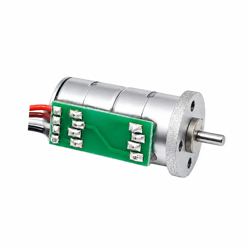
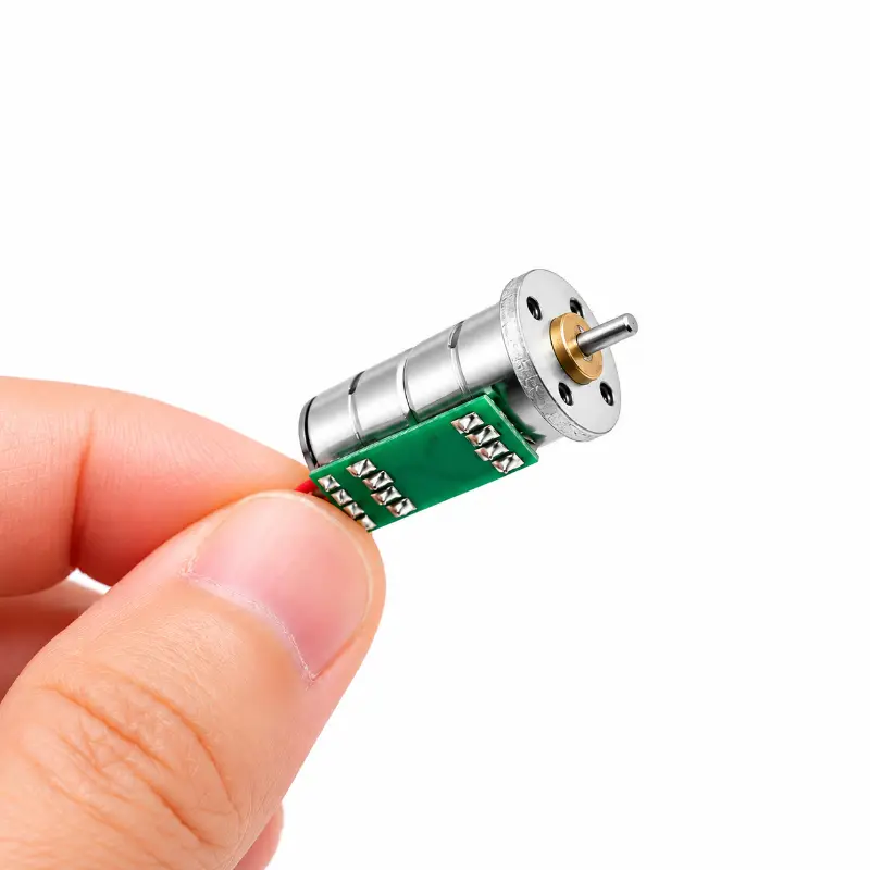
Micro Stepper Motor 10mm Double-Layer PM with 5V and 18° Step Angle
Micro Stepper Motor – 10mm Double-Layer PM Design, 5V 18°
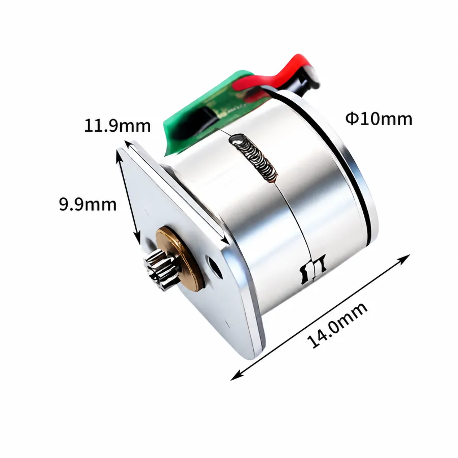
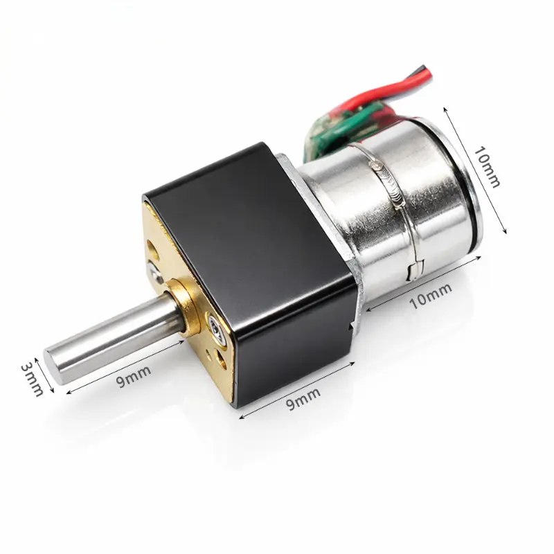
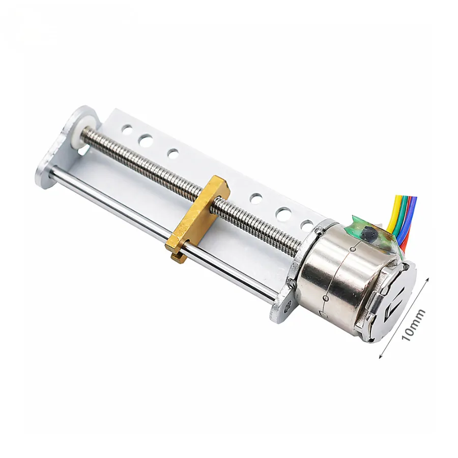
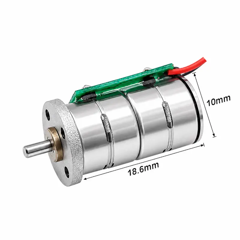
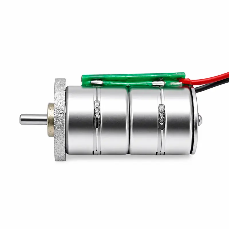
The Kechen Motor KC-10BY2510-N micro stepper motor features a 10 mm diameter double-layer permanent magnet structure designed for miniature rotary positioning mechanisms. Its 18° step angle provides 20 full steps per revolution, while the two-phase excitation system supports controlled incremental movement. The motor incorporates a 2 mm output shaft and four M1.6 mounting holes for mechanical integration.
Electrical And Performance Specifications
| Parameter | Specification |
|---|---|
| Product Model | KC-10BY2510-N |
| Brand | Kechen Motor |
| Motor Type | Permanent magnet stepper motor |
| Motor Structure | Double-layer PM design |
| Rated Voltage | 5.0 V DC |
| Step Angle | 18°/step |
| Excitation Mode | 2-2 phase excitation |
| Resistance Per Phase | 10 Ω |
| Current Per Phase | 630 mA (requires confirmation) |
| Detent Torque | 8 gf·cm |
| Holding Torque | 28 gf·cm |
| Insulation Resistance | ≥ 50 MΩ at 300 V DC |
| Noise Level | ≤ 50 dB(A) |
| Working Temperature | 10–50 °C |
| Technical Data Reference | 800 PPS |
Electrical verification: The specified 630 mA phase current should be checked against the 5 V rated voltage and 10 Ω phase resistance. These voltage and resistance values imply approximately 500 mA under steady DC conditions across one winding. The applicable drive conditions and current measurement require confirmation.
Mechanical Specifications And Mounting Dimensions
| Parameter | Dimension |
|---|---|
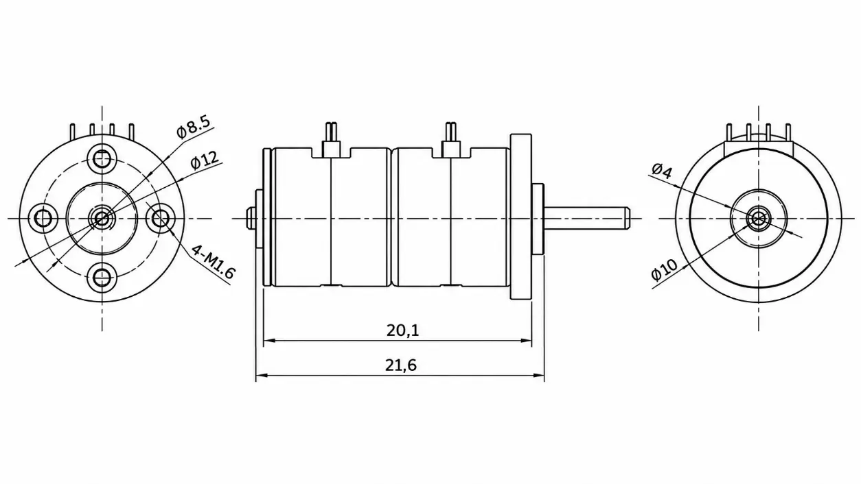
| Motor Body Diameter | Φ10 mm |
| Flange Diameter | Φ12 mm |
| Overall Motor Thickness | 21.6 mm |
| Drawing Reference Length | 20.1 mm |
| Product Image Body Length | 18.6 mm |
| Output Shaft Diameter | Φ2 mm |
| Mounting Holes | 4 × M1.6 |
| Mounting Hole PCD | Φ8.5 mm |
| Rear Center Feature | Φ4 mm |
PCD: Pitch circle diameter. The overall thickness, drawing reference length and product image body length represent different dimensional references and should not be treated as interchangeable.
KC-10BY2510-N Micro Stepper Motor Dimensions And Drawing
The mechanical drawing provides the dimensional references needed to evaluate shaft alignment, mounting clearance and installation space. Confirm the applicable dimensional tolerances before finalizing the assembly.
Micro Stepper Motor Performance Advantages
- Double-Layer PM Construction:
Provides a permanent magnet stepping structure for miniature rotary drive assemblies. - Incremental Positioning:
The 18° full-step angle supports repeatable commanded angular increments when operated with a suitable drive system and load. - Holding Capability:
The specified holding torque provides a reference for evaluating stationary load requirements. Available torque during rotation must be validated separately. - Mechanical Installation:
The 2 mm shaft and four-hole mounting arrangement provide defined interfaces for coupling and fixture design. - OEM Parameter Adjustment:
Shaft length and motor parameters can be reviewed for modification according to the customer’s mechanical and electrical requirements.
OEM Customization And Sample Evaluation
Kechen Motor supports application-based customization of the KC-10BY2510-N miniature stepper motor. Shaft dimensions and electrical parameters can be reviewed against the customer’s installation conditions, driving method and required operating characteristics.
Please provide the required shaft dimensions, supply and driver details, target operating speed, load conditions and expected order quantity. Modified specifications are subject to engineering feasibility and sample validation.
Payment And Order Terms
- Payment Method:
Payment arrangements are confirmed in the official quotation or pro forma invoice. - Order Requirements:
Commercial terms depend on the approved motor configuration and purchase quantity. - Custom Orders:
Engineering specifications and sample requirements should be agreed upon before production authorization.
Shipping And Delivery
- Shipping Options:
International shipment arrangements can be discussed according to destination, quantity and project requirements. - Production Lead Time:
The schedule is confirmed according to the selected configuration, sample approval status and production capacity. - Custom Project Delivery:
Delivery arrangements are established after technical specifications and order requirements have been approved.
Frequently Asked Questions
Q1. What Type Of Micro Stepper Motor Is The KC-10BY2510-N?
It is a double-layer permanent magnet stepper motor with a 10 mm body diameter. It uses a two-phase excitation arrangement and has no specified reduction gearbox.
Q2. How Many Full Steps Are Required For One Revolution?
The 18° step angle corresponds to 20 full steps per mechanical revolution. Actual positioning accuracy depends on the drive sequence, load and operating conditions.
Q3. Can This 5 V DC Stepper Motor Be Connected Directly To A Power Supply?
Controlled stepping requires a suitable driver and excitation sequence. The winding connections, current setting and supply arrangement should be verified before electrical integration.
Q4. Can The Output Shaft Length Be Customized?
Yes. Shaft length and selected motor parameters can be reviewed for OEM customization. Final dimensions and performance requirements must be confirmed through engineering evaluation.
Q5. What Should Be Checked When Selecting This Motor For A Positioning Mechanism?
Verify the available installation space, shaft connection, required positioning increment, operating load and driver compatibility. Holding torque should not be used as a substitute for dynamic torque data.
Q6. Is The Published Drawing Suitable For Final Mechanical Design?
The drawing provides preliminary dimensional references. Final mounting dimensions, tolerances and any customized shaft features should be confirmed using the approved engineering drawing and samples.
Related Motor Specifications
micro stepper motor | miniature stepper motor | small stepper motor | 10mm stepper motor | 5v dc stepper motor | 10mm PM stepper motor | double-layer stepper motor | 18 degree stepper motor | 2mm shaft stepper motor | permanent magnet stepper motor | 2-phase stepper motor | 5 V DC | 18° step angle | 10 mm motor diameter | 2 mm output shaft | 4 × M1.6 mounting holes | KC-10BY2510-N | Kechen Motor
Specifications are for reference only. Final parameters should be confirmed based on approved samples and project requirements.