

Micro Motor Blogs
How to Choose the Right Metal Gear Motor for High-Load Industrial Applications
1. Introduction
Industrial automation relies heavily on robust power transmission systems capable of enduring severe mechanical stress, thermal fluctuations, and continuous operation cycles. When engineering heavy-duty machinery, selecting an appropriate metal gear motor dictates whether a system achieves long-term durability or suffers premature transmission failure due to tooth stripping or thermal overload. Unlike consumer-grade electronics, industrial environments demand drive components that maintain structural integrity under high radial and axial loads. Balancing output torque, gear reduction ratios, and thermal dissipation properties is essential for engineers specifying mechanical architectures for automated manufacturing lines.
2. Understanding Core Technical Requirements
Designing high-load industrial systems requires a precise assessment of operational constraints, duty cycles, and mechanical inertia. Engineers must differentiate between continuous duty cycles, which dictate thermal limits, and peak load demands that test the yield strength of internal gearing components. In many multi-stage reduction assemblies, system designers integrate a high speed dc motor as the primary power source before mechanical gear reduction decreases velocity and multiplies torque. For instance, in automated sorting conveyors, the prime mover operates at high rotational speeds, requiring a robust reduction stage to handle sudden load spikes when heavy packages impact the belt line. Understanding these baseline parameters prevents premature motor burnout and ensures that the power transmission path remains stable under continuous industrial stress.
3. Key Selection Criteria for Industrial Applications
Torque, Gear Reduction, and Material Selection
The primary advantage of utilizing a metal gear motor over thermoplastic alternatives lies in its superior load-bearing capacity and resistance to deformation under extreme mechanical stress. Spur and planetary gear arrangements constructed from hardened steel or brass withstand high bending moments and shock loads without tooth fracture, ensuring a stable integration into high-stress machinery.
Speed, Efficiency, and Thermal Management
Matching output revolutions per minute (RPM) with application requirements ensures optimal mechanical efficiency. Friction within gear meshes generates heat; therefore, thermal management is a critical design parameter. When continuous heavy lifting is required at low velocities, engineers frequently select a high torque low rpm dc motor configuration to eliminate the need for excessive external reduction gearboxes, thereby reducing mechanical complexity and system footprint.
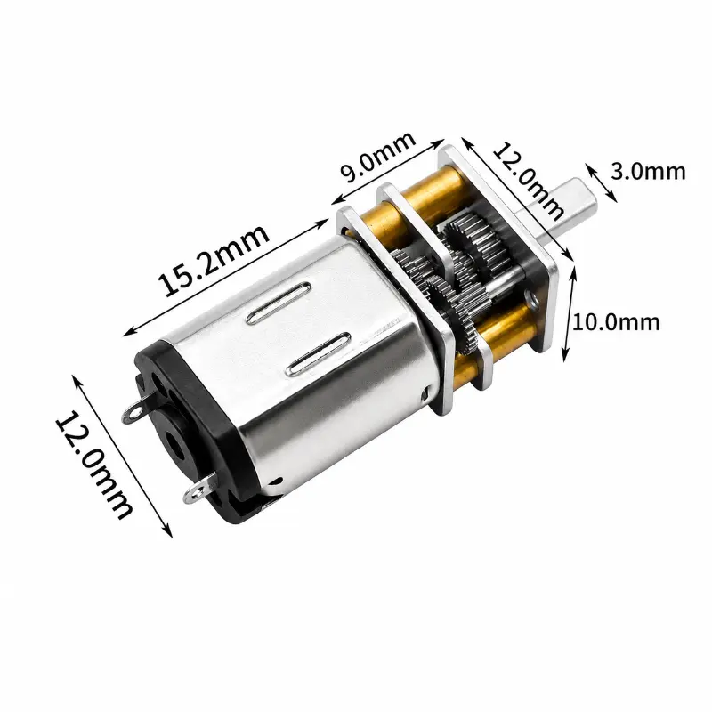
KC-N20 Miniature Gear Motor
4. Evaluating Form Factor and Space Constraints
Modern industrial machinery frequently operates within strict physical limitations, requiring drive components that deliver high power density without expanding the overall equipment envelope. When designing automated guided vehicles (AGVs) or compact medical diagnostic equipment, engineers must specify a miniature gear motor to fit within confined structural chassis while still delivering adequate torque output. Evaluating these physical dimensions involves analyzing shaft alignments, housing configurations, and mounting flange layouts. Properly deployed miniature gear motors enable seamless mechanical integration into space-restricted mechanisms, such as robotic end-effectors for pick-and-place operations or portable infusion pump drive systems, ensuring that structural clearances are maintained without compromising drive rigidity.
5. Tailoring Motor Specifications to Specific Use Cases
Industrial applications vary widely, demanding tailored motor configurations to match specific functional requirements. In heavy-duty material handling and industrial conveyor systems, drive units must endure high starting torque and constant directional shifts. Conversely, precision robotics and automated guided vehicles (AGVs) rely on finely tuned secondary control loops. In such scenarios, incorporating a small gear motor or a micro dc motor into secondary actuation mechanisms—such as automated latching locks, optical sensor adjustments, or valve positioners—provides the necessary precise linear or rotational movement. For example, an automated packaging line uses miniature geared drives to adjust sealing jaw clearances with high repeatability, proving that even minor drive elements dictate overall system accuracy.
6. Common Pitfalls to Avoid During Selection
Engineering teams occasionally encounter operational failures due to overlooked design variables during the metal gear motor selection phase. A frequent oversight involves neglecting mechanical backlash, which introduces dead zones in positioning accuracy during frequent directional reversals. Another critical error is underestimating starting torque requirements, leading to motor stall conditions when overcoming static friction in heavy-duty machinery. Furthermore, failing to account for environmental factors—such as exposure to industrial lubricants, ambient dust, or moisture—can accelerate brush wear and compromise bearing integrity. Addressing these variables early in the design phase prevents costly prototype redesigns and field failures.
7. Conclusion and Frequently Asked Questions
Selecting an appropriate power transmission solution requires a rigorous evaluation of torque curves, gear materials, thermal limits, and spatial constraints to guarantee long-term operational reliability in demanding industrial environments.
Frequently Asked Questions (FAQ)
Metal gears offer significantly higher tensile strength and resistance to thermal degradation. In heavy-duty sorting conveyors where sudden load spikes occur, plastic gears are prone to thermal softening and tooth stripping, whereas hardened steel or brass configurations maintain structural integrity under continuous high-stress operations.
Introducing a multi-stage gear reduction box multiplies output torque while decreasing rotational speed, allowing the primary DC motor to operate within its optimal efficiency zone. This reduction prevents excessive armature current draws and minimizes thermal stress on the winding coils during high-load operations.