

Micro Motor Blogs
How to Choose the Smallest Stepper Motor for Compact Medical Devices Without Sacrificing Torque
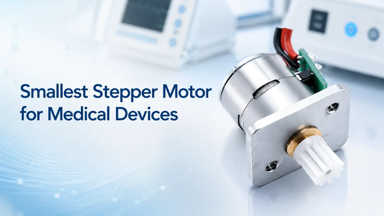
Modern medical electronics, ranging from ambulatory infusion systems to portable diagnostic analyzers, face continuous physical footprint reductions. Designing actuation sub-assemblies inside tight housing envelopes creates severe mechanical bottlenecks. When engineering teams specify the smallest stepper motor for an integrated drive assembly, the primary challenge remains maintaining sufficient holding and pull-out torque without causing excessive thermal dissipation or step loss. Achieving exact positioning accuracy within restricted space constraints requires evaluating magnetic flux density, gear reduction mechanisms, and current management protocols.
1. Introduction
Miniaturization in healthcare devices—including wearable insulin pumps, automated liquid handlers, and handheld surgical tools—demands precise positioning actuators with minimal structural volumes. Reducing motor frame size inherently decreases internal copper volume and magnetic pole surface area, directly lowering generated magnetic flux. Consequently, specifying a small stepper motor often introduces systemic trade-offs between physical size and mechanical force output. Engineering teams must systematically evaluate rotor geometry, phase current management, and mechanical amplification to secure the smallest stepper motor capable of meeting dynamic load requirements under continuous operational cycles.
2. Understanding the Trade-Off: Size vs. Torque Density
The electromagnetic torque (τ) produced by a permanent magnet or hybrid stepper motor relies on the interaction between stator flux and rotor permanent magnets. For a given winding configuration and magnetic material grade, electromagnetic torque generally scales with the effective magnetic circuit volume, which is proportional to rotor diameter squared multiplied by stack length. This relationship explains why frame reduction directly impacts torque output:
Where:
- Dr represents the active rotor outer diameter.
- Lr represents the active stack length of the rotor.
When scaling down frame dimensions, rotor volume shrinks rapidly. Decreasing stator space restricts the cross-sectional wire area of the phase windings, which forces the use of higher AWG (thinner) wire. Thinner magnet wire raises winding resistance (R), accelerating Joule heating (I²R losses) and placing stricter limits on maximum allowable drive currents before thermal insulation failure occurs.
+-------------------------------------------------------------------+
|               MINIATURIZATION ELECTROMAGNETIC CONSTRAINTS        |
+-------------------------------------------------------------------+
|                                                                   |
|   Stator Envelope Reduced ---> Winding Window Cross-Section Drops |
|                                              |                    |
|                                              v                    |
|   Thinner Wire (Higher AWG)  <--- Higher Resistance per Turn      |
|               |                                                   |
|               v                                                   |
|   Increased I²R Heat Loss ---> Lower Maximum Continuous Current   |
|                                              |                    |
|                                              v                    |
|   Reduced Rotor Radius (D_r) ---> Lower Holding & Pull-Out Torque|
|                                                                   |
+-------------------------------------------------------------------+
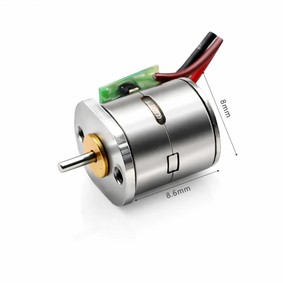
KC-08BY 8mm Miniature PM Stepper Motor
Φ8.0mm · 18°/step · 2-phase 4-wire · Ideal for medical instruments, optical devices, and micro-pumps.
Critical Dynamic Performance Metrics
- Holding Torque: The static torque generated at zero velocity when rated DC current energizes the phases. In medical dosing pumps, sufficient holding torque prevents back-driving caused by fluid line pressure spikes.
- Pull-Out Torque: The maximum dynamic torque a motor delivers at a given speed without slipping steps. In micro-actuation, high pull-out torque prevents step loss during rapid acceleration profiles.
Relying exclusively on standard NEMA frame ratings (such as NEMA 06 or NEMA 08) can be misleading. Frame designations dictate mounting hole orientation and faceplate geometry, but they do not define internal stator pole geometry, coil fill factor, or magnet grades. A custom-engineered micro stepper motor with optimized magnetic circuit design can achieve higher torque density than a non-optimized standard off-the-shelf unit of comparable frame size, though it cannot overcome fundamental volume-based electromagnetic constraints.
3. Key Strategies to Maximize Torque in Miniature Stepper Motors
Overcoming torque degradation in sub-15 mm motor frames requires targeted electromechanical engineering modifications rather than simple physical scaling.
Strategy 1: Integrating Precision Gearheads
Integrating a high-precision gear train multiplies output torque while operating the motor at higher, thermally efficient rotational speeds. Implementing a high-efficiency geared stepper motor allows engineers to step down motor speed and scale shaft torque according to the gear ratio (i) and gear efficiency (η):
For example, pairing an 8 mm direct-drive motor producing 0.5 mN·m holding torque with a 25:1 planetary gearhead (η ≈ 75%) elevates usable continuous torque to approximately 9.4 mN·m. This approach enables compact form factors to achieve torque levels otherwise requiring significantly larger direct-drive motors, though engineers must account for gearhead backlash, efficiency variation under load, and added rotational inertia in dynamic response calculations.
Strategy 2: Advanced Magnetic Materials and Winding Configurations
Engineers can increase magnetic field intensity without altering physical dimensions by optimizing magnetic material selection and coil winding density.
- Neodymium-Iron-Boron (NdFeB) Magnets: Replacing standard ferrite rotor magnets with sintered N52 or N54 grade NdFeB magnets maximizes magnetic flux density in the air gap, increasing torque constant (Kt). However, NdFeB magnets exhibit higher temperature coefficients and require careful thermal management in continuous-duty applications.
- Optimized Copper Fill Factor: Utilizing automated precision winding techniques with optimized slot geometry can increase the copper fill factor compared to conventional bobbin-based methods. Higher copper density in stator slots lowers overall phase resistance for a given turn count, suppressing thermal generation at operating current levels. Typical fill factors range from 35–50% for standard designs to 55–65% for optimized configurations.
Selecting a refined high torque micro stepper motor design allows engineering teams to maximize torque output within tight spatial constraints.
Strategy 3: Driver Optimization and Current Management
Drive electronics directly affect motor output torque and thermal characteristics.
- Current Chopping (PWM Drivers): Constant-current chopper drives supply bus voltages higher than the rated motor voltage to overcome winding inductance (L). Fast current rise times (di/dt = V/L) extend peak pull-out torque higher into the speed curve.
- Microstepping with Current Profiling: Operating a miniature stepper motors assembly under 1/16 or 1/32 microstepping smooths out current sine waves, dampening mechanical resonance points where torque dips typically occur.
- Closed-Loop Control with Position Feedback: Integrating magnetic encoders provides position feedback, allowing the drive to adjust current based on actual mechanical load rather than continuous maximum rated current. This prevents thermal overload inside sealed medical device enclosures. Note that true vector control is typically implemented in servo systems; stepper motor closed-loop systems more commonly use position-error-based current adjustment.
4. Medical Application Focus: Precision Dosing and Actuation
Sub-miniature stepper motors serve as primary actuators across precise fluidic and mechanical medical systems.
+--------------------------------------------------------------------+
|               INFUSION PUMP DRIVE TRAIN SCHEMATIC                  |
+--------------------------------------------------------------------+
|                                                                    |
|  [ Closed-Loop Driver ] ---> [ Micro Stepper Motor (8mm-12mm) ]   |
|                                        |                           |
|                                        v                           |
|                            [ Precision Gearhead ]                  |
|                                        |                           |
|                                        v                           |
|                            [ Lead Screw Drive Shaft ]              |
|                                        |                           |
|                                        v                           |
|                            [ Syringe Plunger Actuator ]            |
|                                                                    |
+--------------------------------------------------------------------+
Application Instance: Infusion and Syringe Pumps
In portable ambulatory pumps, linear fluid displacement requires continuous sub-microliter resolution. Installing the smallest stepper motor for infusion pumps enables compact form factors without sacrificing fluid line pushing force (occlusion pressure).
- Positioning Accuracy: Open-loop step control eliminates continuous position sensor checks, preserving battery power while maintaining reliable displacement volume per pulse.
- Noise and Vibration: Low-vibration microstepping prevents acoustic noise, improving patient comfort during wear or bed-side monitoring.
- ISO 13485 Compliance: Manufacturing components under ISO 13485 quality management systems ensures documented processes for traceability, material control, and consistent production. ISO 13485 establishes management system requirements rather than specifying product performance metrics such as step consistency or wear patterns directly.
5. Selection Checklist and Engineering Considerations
When finalizing a motion sub-assembly specification, balance electrical and mechanical limits using this structured evaluation checklist:
- Thermal Dissipation Limits: Calculate continuous thermal resistance (Rth) inside sealed housings. Ensure peak frame temperatures stay under maximum coil insulation tolerances (typically Class B at 130°C or Class F at 155°C).
- Radial and Axial Shaft Loading: Miniature motor bearings are sensitive to side loads. Verify gearhead pinion forces against manufacturer-specified radial shaft limits, which vary significantly by bearing type and shaft diameter. For sub-10 mm shafts, radial load ratings typically range from 3 N to 15 N depending on bearing configuration.
- Duty Cycle Requirements: Differentiate between intermittent actuation (e.g., valve toggling every 10 minutes) and continuous rotation (e.g., peristaltic pumping). High duty cycles require active driver current reduction during dwell times.
- Mechanical Interface Integration: Specify direct lead screw integration or custom shaft flats directly on the rotor shaft to eliminate flex couplings, saving axial space and removing mechanical backlash points.
6. Custom vs Standard Miniature DC Motors Cost Comparison
When specifying actuation solutions for medical devices, engineering teams frequently face the decision between standard catalog motors and custom miniature DC motor configurations. Understanding the cost structure and value proposition of each approach is essential for optimizing both performance and project economics.
Standard Motor Economics
Standard off-the-shelf miniature DC motors offer immediate availability, established reliability data, and unit costs that decrease predictably with volume. For a custom miniature DC motor manufacturer, standard product lines represent amortized development costs across thousands of units, resulting in lower per-unit pricing even at moderate volumes. However, standard motors may require additional mechanical adapters, external gearing, or compromise on performance specifications when integrated into space-constrained medical devices.
Custom Motor Value Proposition
Engaging a customized micro DC motor supplier for application-specific designs introduces upfront engineering and tooling investments. These non-recurring engineering (NRE) costs typically range from $5,000 to $50,000 depending on complexity, magnetic material selection, and certification requirements. For small volume custom DC motor production runs (under 1,000 units annually), per-unit costs remain higher than standard equivalents. The economic crossover point where custom designs achieve competitive unit pricing generally occurs between 5,000 and 10,000 units annually, assuming multi-year production commitments.
The primary value drivers for custom configurations include:
- Volume Reduction: Integrated gearheads, lead screws, or custom shaft geometries eliminate external mechanical components, reducing overall assembly volume by 20–40% compared to standard motor plus adapter solutions.
- Performance Optimization: Custom winding configurations, magnet grades, and thermal management tailored to specific duty cycles can improve torque density by 15–30% within the same frame size.
- Regulatory Streamlining: Custom designs manufactured under ISO 13485 with complete material traceability and biocompatibility documentation accelerate FDA submission processes for medical device OEMs.
Total Cost of Ownership Analysis
Evaluating how to choose a miniature DC gear motor for robotics or medical applications requires analyzing total cost of ownership beyond unit pricing. Standard motors may appear cost-effective initially but can incur hidden costs from additional integration components, calibration procedures, and field reliability issues when operated outside their design envelope. Custom micro DC motor for medical devices configurations, while requiring higher initial investment, often reduce system-level costs through simplified assembly, reduced component count, and optimized performance margins.
For high torque miniature DC motor 12v requirements in portable medical equipment, custom designs enable precise matching of voltage, torque, and thermal characteristics to battery power budgets—an optimization rarely achievable with standard catalog selections.
7. Conclusion
Balancing physical size and mechanical force output in micro-actuation systems requires optimizing magnetic materials, gear reduction mechanics, and current management strategies rather than relying on motor size alone. Contact our engineering team today to request technical consultation and custom performance samples for your medical device project.
Torque‑Speed Characteristic — Miniature Stepper Motor
Pull‑out torque vs. speed for a typical 10 mm frame micro stepper
▲ Holding torque at zero speed · ▼ Rapid drop above 600 rpm due to inductive reactance
Frequently Asked Questions
FAQ 1: Does microstepping increase the maximum holding torque of a micro stepper motor?
No. Microstepping improves incremental positioning resolution and dampens mechanical resonance, but it does not increase maximum holding torque. The incremental torque per microstep drops as step resolution increases. For example, at 1/16 microstepping, the restoring torque available at each microstep position is approximately 9.9% of the full-step holding torque. The total holding capability of the motor remains determined by the full-step rated current and magnetic circuit design. To maintain position accuracy during microstepping, current profiles must be held steadily at the appropriate vector levels.
FAQ 2: Why does a small stepper motor generate significantly more heat than a larger motor with the same load?
Smaller motors have smaller surface areas for convective heat transfer and reduced thermal mass. Because smaller winding slots require thinner wire (higher resistance), I²R electrical losses convert into concentrated heat much faster. Without dynamic current reduction or heat sinking, micro motors can quickly reach insulation temperature limits. Additionally, smaller motors typically operate at higher current densities to achieve comparable torque output, further exacerbating thermal challenges.
FAQ 3: Why should I choose a geared stepper motor over a direct-drive motor of the same total size?
Direct-drive micro motors are fundamentally limited by rotor volume constraints on torque generation. A smaller direct-drive motor operated at higher speeds with a precision planetary or spur gearhead scales output torque by the gear ratio, often producing higher usable torque than a larger direct-drive motor of equivalent total package volume. However, this advantage must be weighed against gearhead characteristics including backlash (typically 0.5–3° for precision planetary designs), efficiency variation with load and speed, audible noise from gear meshing, and reduced maximum output speed. For applications requiring high dynamic response or minimal backlash, direct-drive configurations with oversized motors may be preferable despite larger volume.