

Micro Motor Blogs
N20 Motor Dimensions and Specifications for Mechanical Design
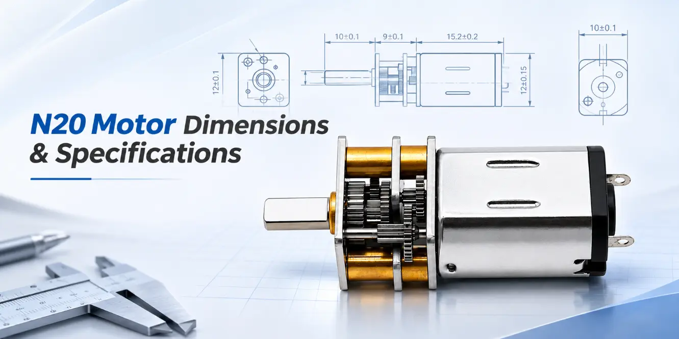
N20 motor dimensions determine whether a miniature drive assembly fits its mounting space, aligns with the driven mechanism, and provides sufficient clearance for the output shaft. The N20 motor typically has a rectangular body cross-section of approximately 12 × 10 mm, but its overall length varies with the motor configuration, gearbox, encoder, and output shaft.
For mechanical design, the motor body alone does not provide enough information. Engineers must also consider gearbox length, shaft projection, mounting hole positions, manufacturing tolerances, and the space required for electrical connections. A motor that fits inside the housing may still interfere with adjacent components once its shaft or encoder is installed.
This guide examines n20 motor dimensions using published Kechen Motor specifications, model comparisons, shaft arrangements, mechanical drawings, and electrical performance data. The objective is to help engineers identify installation requirements before preparing an assembly drawing or ordering samples.
N20 Motor Dimensions: Motor Body and Gearbox
Standard N20 Motor Body Size

The N20 is a miniature brushed DC motor commonly used in small drive mechanisms. Its nominal body cross-section is approximately 12 × 10 mm, although the housing geometry and axial length depend on the actual motor series.

The main distinction when evaluating n20 motor size is between the bare motor and the complete geared assembly. The bare motor has its own output shaft, while a geared version incorporates a reduction housing and a separate gearbox output shaft. The dimensions of these two arrangements should not be treated as interchangeable.
For example, the Kechen Motor KC-GM12-N20-09190-3.7V has a published motor body length of 15.2 mm and a gearbox length of 9 mm. Its motor-and-gearbox housing length is approximately 24.2 mm, excluding the projecting lead screw. This is a configuration-specific reference, not a universal N20 motor length.
When examining n20 dc motor dimensions, three groups of measurements should be recorded separately:
- Motor body dimensions: the housing cross-section, axial length, and terminal arrangement.
- Gearbox dimensions: housing length, mounting face, output shaft position, and attachment features.
- Complete assembly dimensions: the full installation envelope, including the motor, gearbox, shaft, encoder, and other projecting components.
These measurements are particularly important in small optical positioning mechanisms, electronic locks, and instrument actuators where the surrounding housing provides limited clearance. Electrical terminals may also need additional space for solder joints, insulation, or connector routing.
N20 Gear Motor Dimensions and Model Comparison

A reduction gearbox changes the axial length and mounting geometry of an N20 motor. Spur gearboxes commonly use a rectangular housing, while planetary gearboxes have a different internal arrangement and may require different mounting provisions.
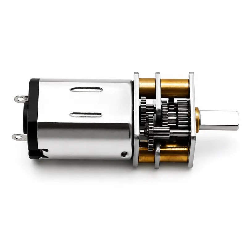
The following table compares published dimensions for selected Kechen Motor configurations. Values are based on the corresponding product specifications. Final installation measurements should be confirmed against the mechanical drawing of the selected configuration.
| Motor Model / Configuration | Motor Body Length | Gearbox Length | Published Dimensions | Output Configuration |
|---|---|---|---|---|
| KC-GM12-N20-09190-3.7V | 15.2 mm | 9 mm | Approx. 24.2 mm housing assembly, excluding lead screw | 30 mm lead screw with dowel pin |
| KC-GM12-N20-10138 | Requires confirmation | 9 mm | Complete installation length requires confirmation | Spur gearbox with magnetic encoder option |
| KC-GM12-N20 Series, 90 mm M4 Lead Screw Configuration | 15.2 mm | 9 mm | 90 mm published shaft length; complete assembly length requires confirmation | Threaded shaft with encoder |
The comparison demonstrates why n20 gear motor dimensions must be evaluated using the specific product configuration. A gearbox length of 9 mm does not represent the full motor assembly, and a 90 mm shaft specification does not automatically establish the distance from the gearbox mounting face to the shaft tip.
For the 90 mm lead screw version, the complete axial envelope requires confirmation because the published shaft length does not fully establish the coupling position, usable threaded length, or encoder projection. These details should be resolved before the assembly is dimensioned.
Engineers comparing n20 motor dimensions should also distinguish a fixed gearbox housing dimension from a dimension measured between assembly reference surfaces. Using inconsistent references can lead to incorrect total-length calculations.
N20 Motor Dimensions: Output Shafts and Mounting Interfaces
N20 Motor Shaft Size and Output Types

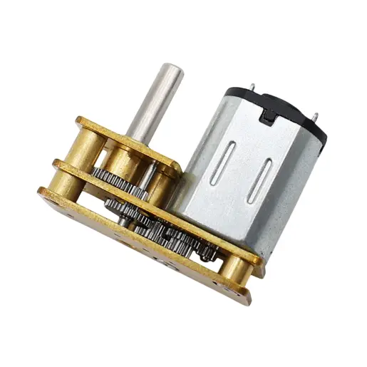
The output shaft determines how the motor transfers rotation to the surrounding mechanism. Shaft diameter, geometry, extension length, and manufacturing tolerance affect the connection to gears, pulleys, couplings, and threaded drive components.
There is no single n20 motor shaft size applicable to every configuration. A bare N20 motor shaft and a geared motor output shaft serve different mechanical functions, and their dimensions should be checked independently.
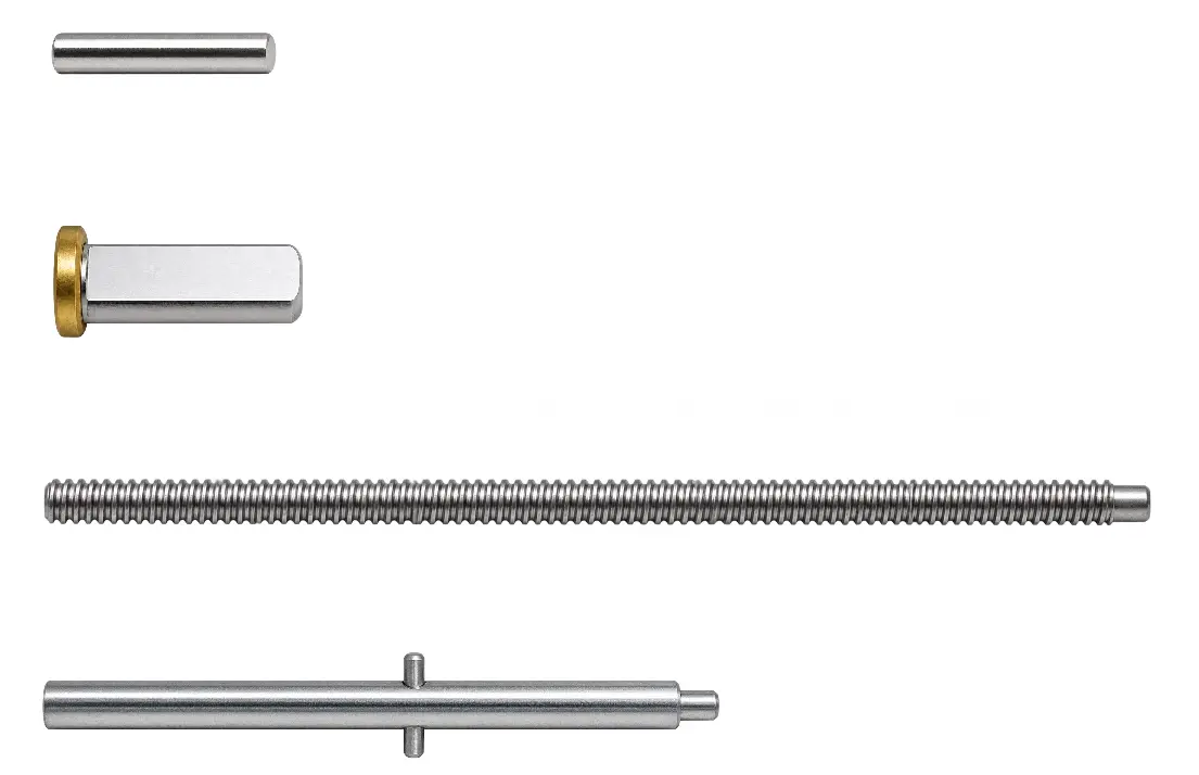
Common shaft configurations include:
- Round shaft: suitable for appropriately designed press-fit components, clamping hubs, or couplings. The fit depends on the shaft and bore tolerances.
- D-shaped shaft: provides a machined flat for mating components designed to transmit torque through the corresponding geometry.
- Threaded shaft: used with a suitable nut and support mechanism to convert rotary motion into linear displacement.
- Custom shaft: may involve modified length, diameter, flat geometry, or end features, subject to mechanical evaluation.
The KC-GM12-N20-09190-3.7V provides a useful example of a nonstandard output arrangement. Its published specifications identify a 3 mm lead screw diameter, a 30 mm lead screw length, a 2 mm shaft-end diameter, and a 1 mm pin feature.
These dimensions describe the specified assembly. They do not establish the thread pitch, dimensional tolerances, or allowable shaft loading. Those details require confirmation from the appropriate drawing or engineering data.
Another KC-GM12-N20 configuration uses an M4 threaded lead screw with a published 90 mm shaft length and magnetic encoder assembly. Its exact configuration must be identified before comparing mounting dimensions with the 30 mm lead screw version.
For a threaded drive, the required nut travel must be considered separately from the shaft’s nominal length. A mechanical design may provide enough space for the lead screw but insufficient room for the nut, moving carriage, and end-of-travel clearance.
Mounting Hole Positions, Shaft Alignment and Tolerances
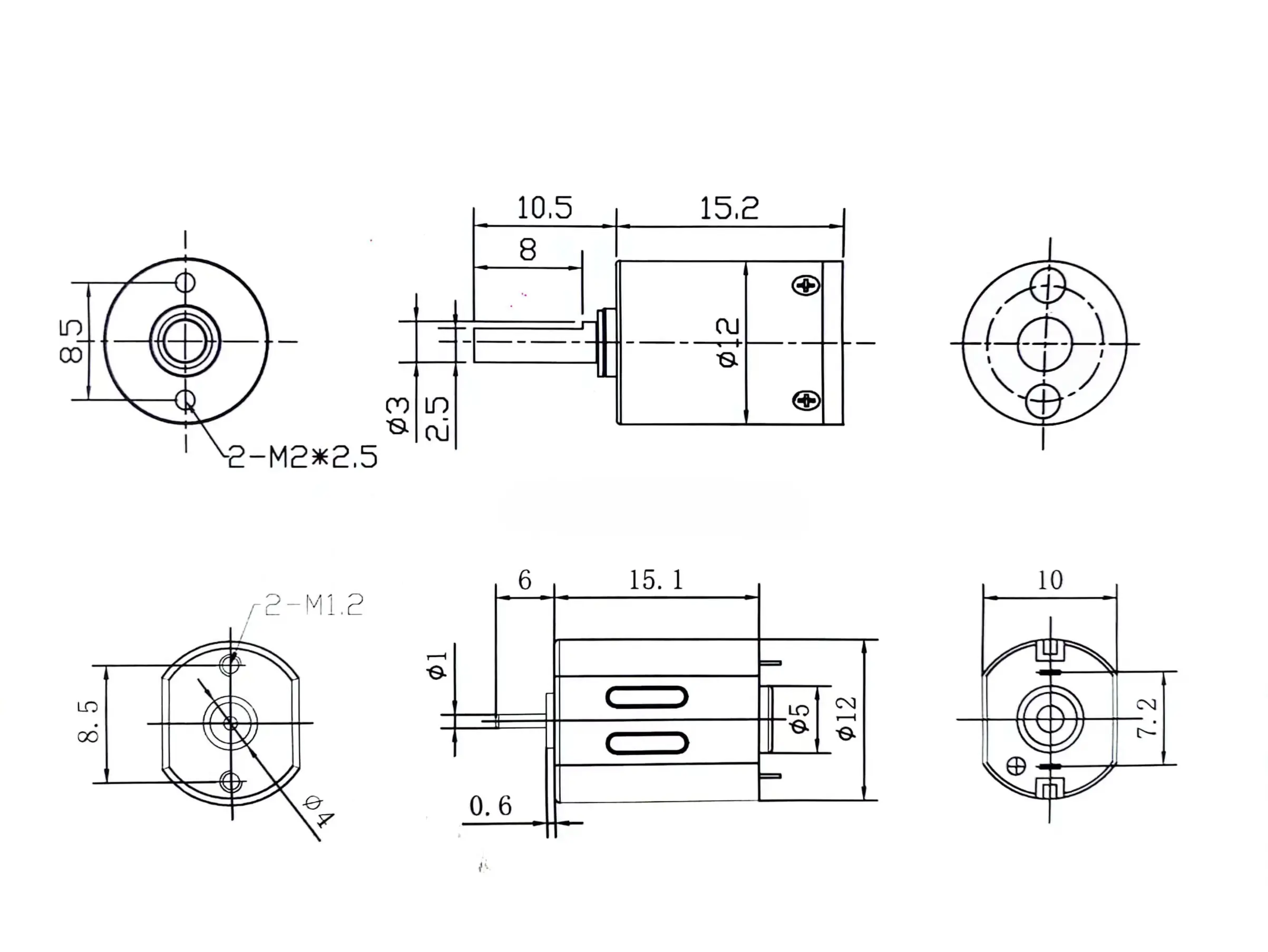
Mounting geometry is another important part of n20 motor dimensions. The mounting interface determines whether the gearbox can be secured without introducing unwanted loads into its output shaft.
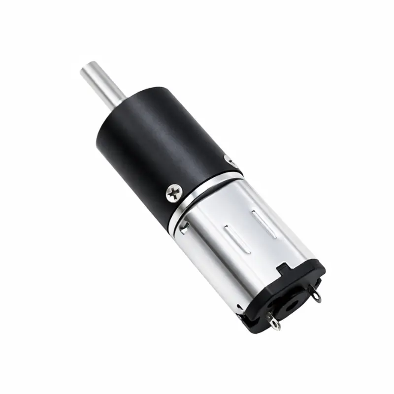
For the KC-GM12-N20-09190-3.7V, the published specifications include a 12 × 12 mm mounting face and an M1.6 × P0.35 mounting thread designation.
The mounting face dimension must not be confused with the mounting hole center distance. Hole spacing, hole depth, and shaft center position should be taken from the corresponding engineering drawing.
Before designing a mounting bracket, verify the following dimensions:
- Mounting hole center-to-center spacing.
- Thread size, depth, and permissible screw engagement.
- Output shaft centerline relative to the mounting surface.
- Shaft diameter and available engagement length.
- D-flat dimensions or thread details where applicable.
- Relevant shaft runout, axial movement, and positional tolerances.
Consider a valve positioning mechanism where the gearbox shaft connects to a rigid coupling. If the shaft and driven component are not aligned, the coupling may introduce radial loads. Depending on the bearing arrangement and coupling flexibility, this can increase friction or accelerate mechanical wear.
A similar problem occurs when a pulley bore matches the nominal shaft diameter but uses an unsuitable tolerance. The connection may slip, require excessive assembly force, or cause deformation.
For these reasons, n20 motor dimensions should be reviewed together with the mating component’s tolerances rather than as isolated measurements.
N20 Motor Drawings, CAD Files and Tolerances
How to Read N20 Motor Dimension Drawings
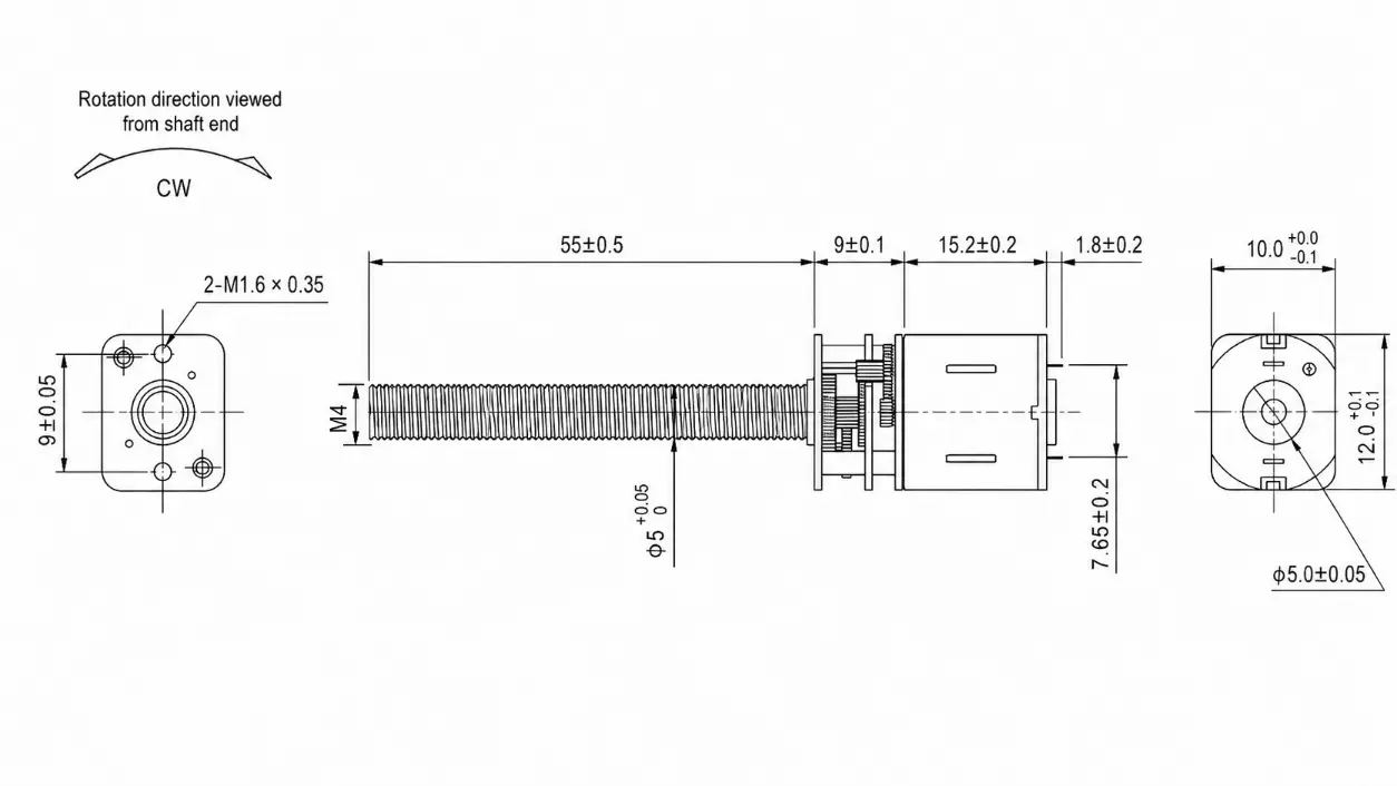
A mechanical drawing establishes the reference geometry needed to position a motor within an assembly. For n20 motor dimensions, the most useful references are usually the gearbox mounting face, shaft centerline, axial housing dimensions, and output shaft extension.
Begin by identifying the complete model designation. A drawing for an N20 motor with a spur gearbox may not apply to a planetary gearbox or an encoder-equipped assembly, even when the products have similar external dimensions.
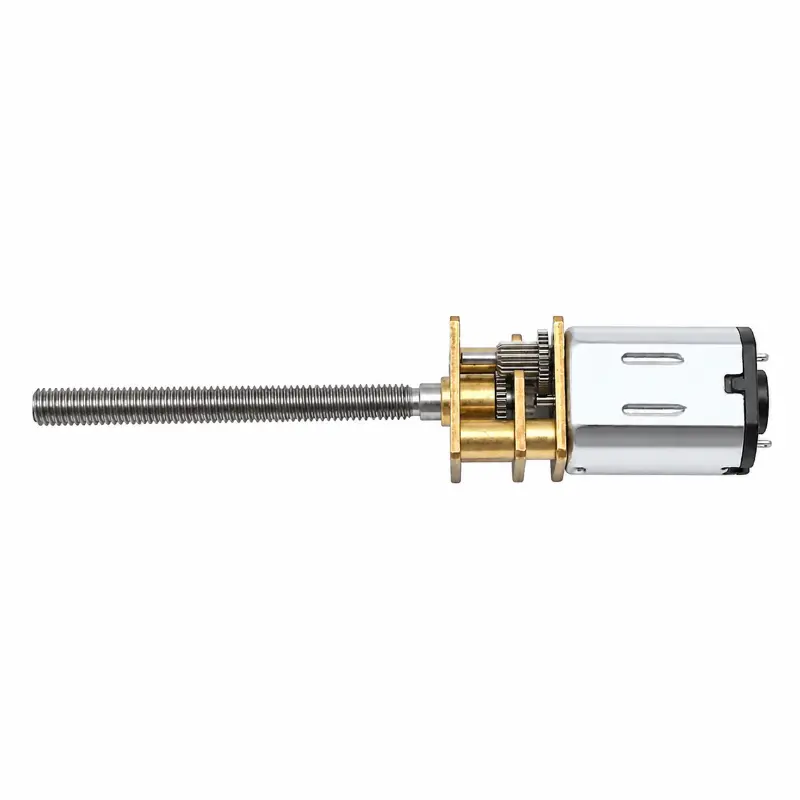
Next, identify the dimensional reference points. For example, an output shaft dimension may be measured from the gearbox front surface, while the overall assembly dimension may be measured from the rear motor cover. These values should not be added without considering their reference surfaces.
Drawing revisions are also important. A modification to the shaft end, connector position, or gearbox housing can affect mechanical compatibility without changing the basic N20 designation.
Engineers should distinguish nominal dimensions from dimensions with controlled tolerances. A nominal housing width does not, by itself, indicate the maximum permitted width or the clearance required for assembly.
N20 Motor CAD Models and Engineering Documents
Designers searching for n20 motor cad files generally need geometry that can be placed into a mechanical assembly to evaluate mounting, interference, and component positioning.
Two-dimensional drawings are suitable for checking mounting hole positions, gearbox length, and shaft geometry. Three-dimensional models in formats such as STEP can support assembly placement and interference analysis when the corresponding model is available.
However, a CAD model does not automatically define manufacturing tolerances, allowable shaft loading, electrical performance, or expected operating life. Those requirements must be supported by separate engineering information.
Kechen Motor provides model-specific drawing and performance documents for selected N20 motors. The N20 Motor product range includes published technical resources covering different motor and gearbox configurations.
Available document listings include 6 V, 12 V, and 24 V motor configurations. The complete model designation, shaft geometry, and drawing revision should be checked before using any document for production design. Drawing and performance-sheet identifiers must also be consistent with the selected assembly.
The availability of STEP files or other three-dimensional CAD formats depends on the requested configuration and requires confirmation.
When requesting mechanical data, provide the complete motor model, voltage, gearbox type, gear ratio, output shaft arrangement, and required file format. This helps ensure that the supplied drawing corresponds to the intended installation.
How Gearboxes and Encoders Affect Overall Length
Comparing Bare Motors, Gearboxes and Encoder Configurations

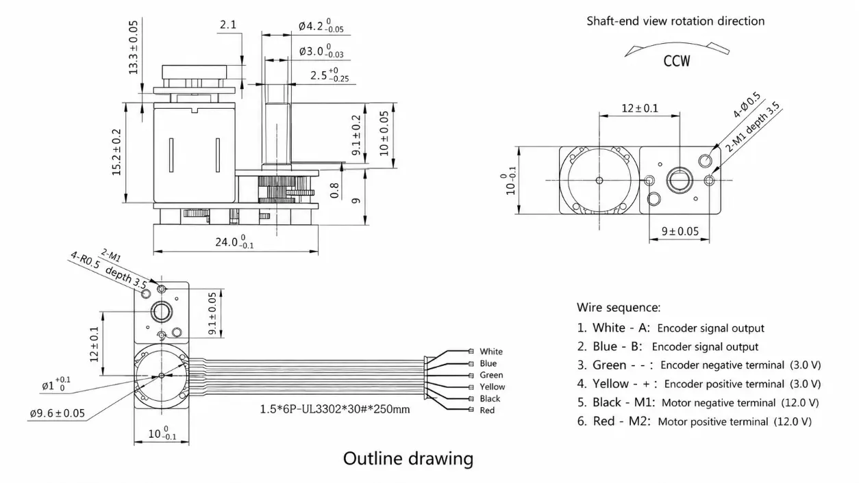
Two assemblies using similar N20 motor bodies may require different installation spaces. The gearbox, encoder position, output shaft arrangement, and cable routing all affect the mechanical envelope.

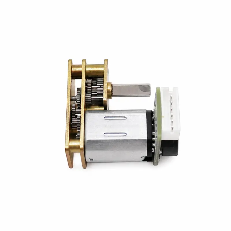
A bare N20 motor has no reduction gearbox. Its output shaft rotates at motor speed, and its mechanical dimensions are primarily determined by the motor housing, shaft, and electrical terminals.
An N20 spur gear motor adds a reduction housing. The gearbox output shaft becomes the primary mechanical interface, and its mounting position must be referenced independently from the motor housing.
For an encoder-equipped version, additional clearance may be required behind the motor. The KC-GM12-N20-10138 series includes a magnetic encoder option with a published 9 mm spur gearbox length. The 9 mm measurement refers to the gearbox, not the full encoder-equipped assembly.
Threaded-shaft versions introduce another difference. Their axial envelope may extend considerably beyond the gearbox because the lead screw must accommodate the moving mechanism.
The following table summarizes the mechanical differences that should be evaluated when comparing n20 motor dimensions across configurations.
| Configuration | Gearbox Structure | Encoder | Output Interface | Primary Installation Consideration |
|---|---|---|---|---|
| Bare N20 DC Motor | None | Depends on configuration | Motor shaft | Motor housing, shaft projection, and terminals |
| KC-GM12-N20-09190-3.7V | 9 mm spur gearbox | Not specified | 30 mm lead screw | Housing length, shaft projection, and driven mechanism |
| KC-GM12-N20-10138 | 9 mm spur gearbox | Magnetic encoder option | Configuration-dependent output shaft | Gearbox, motor body, rear encoder, and wiring |
| KC-GM12-N20 Series, 90 mm M4 Lead Screw Configuration | Spur gearbox | Magnetic encoder | M4 threaded lead screw | Complete shaft projection, coupling, encoder, and nut travel |
| KC-GMP12-N20 Series | Planetary gearbox | Depends on configuration | Configuration-dependent | Planetary housing dimensions and mounting interface |
The planetary series is included as a separate mechanical arrangement because its gearbox structure differs from the spur reduction versions. Its installation dimensions should be taken from its own drawing rather than inferred from another N20 gearmotor.
These distinctions matter in optical adjustment modules, laboratory positioning equipment, and automated latching mechanisms where surrounding components restrict the available axial space.
Determining the Complete Installation Envelope
The installation envelope represents the complete space required by the motor assembly and its associated mechanical connections.
For an arrangement with non-overlapping axial sections, a preliminary length estimate can be expressed as:
Add only non-overlapping sections measured from consistent reference surfaces.
This relationship is valid only when the dimensions describe separate physical sections measured from consistent references. Dimensions that include overlapping components must not be added again.
For example, the KC-GM12-N20-09190-3.7V has a published housing assembly length of approximately 24.2 mm excluding its lead screw. That value should not be interpreted as the maximum installed length.
Similarly, a specified 90 mm lead screw length does not necessarily equal the distance between the gearbox face and the far end of the assembled shaft. The exact measurement depends on the mechanical connection and drawing references.
In addition to n20 motor dimensions, the installation assessment should include wiring clearance, connector orientation, screw access, manufacturing variation, and movement of surrounding components.
For a linear positioning mechanism, the motor may fit within the housing while the nut or moving carriage exceeds the available travel space. The entire motion path should therefore be checked, not just the stationary motor assembly.
Reading N20 Motor Electrical and Performance Specifications
Voltage, Speed, Current and Torque
Mechanical compatibility does not establish whether a motor can operate the intended load. N20 motor specifications must be reviewed together with dimensional requirements because the selected motor winding and gearbox configuration determine the available speed and torque.
The principal electrical parameters describe different operating conditions:
- Rated Voltage: the specified operating voltage for a particular motor configuration.
- No-load Speed: rotational speed measured without an externally applied mechanical load.
- Rated Speed: speed at the specified rated operating point.
- No-load Current: electrical current drawn under no-load test conditions.
- Rated Current: current associated with the specified rated load.
- Rated Torque: torque at the defined rated operating point.
- Stall Current: current when the motor is prevented from rotating under specified electrical conditions.
- Stall Torque: torque produced at zero rotational speed under the specified test conditions.
In a small dispensing mechanism, a motor may reach its published no-load speed when disconnected from the drive load but rotate more slowly when dispensing resistance increases. Rated speed and rated torque are therefore more relevant to normal operation than no-load speed alone.
Stall current is particularly important when selecting the motor driver and considering abnormal operating conditions. It should not be confused with continuous rated current, and sustained stall operation should not be assumed permissible.
The measurement position also matters. Bare-motor speed is measured at the motor shaft, while gearmotor output speed is measured after the reduction gearbox. The two values cannot be compared without accounting for the gear ratio.
Comparing N20 Gear Motor Specifications
The following values are published reference specifications for selected Kechen Motor configurations. They illustrate how output characteristics differ between motor windings and reduction ratios. Final performance should be verified using the applicable test data and approved samples.
| Motor Model | Rated Voltage | Gear Ratio | No-load Output Speed | Rated Output Speed | Published Rated Torque |
|---|---|---|---|---|---|
| KC-GM12-N20-09190-3.7V | 3.7 V | 30:1 | 367 rpm | 293 rpm | 0.042 kg·cm |
| KC-GM12-N20-10138 | 3.7 V | 30:1 | 500 rpm | 410 rpm | 0.04 kg·cm |
| KC-GM12-N20-07310-12V | 12 V | 10:1 | 2300 rpm | Requires confirmation | 0.016 kg·cm |
The table shows that motors with the same nominal reduction ratio can have different output speeds. The KC-GM12-N20-09190-3.7V and KC-GM12-N20-10138 both have published 30:1 configurations, but their listed no-load output speeds differ.
When comparing n20 gear motor specifications, this difference should be considered alongside the motor winding, electrical operating point, gearbox efficiency, and mechanical load.
A higher reduction ratio generally lowers the output speed and increases the torque available at the gearbox output, subject to gearbox efficiency and load limitations. It does not automatically establish a higher permissible continuous operating torque.
Gear tooth strength, output shaft support, operating temperature, and duty cycle may limit the usable torque before the motor reaches its theoretical capability.
For a motorized locking mechanism, the gearbox may provide sufficient torque for a short actuation cycle but require further assessment if the mechanism is expected to operate repeatedly under sustained load.
Published n20 motor specifications should therefore be treated as reference data until the required operating points and actual load conditions are confirmed. Detailed torque calculations and reduction ratio selection are better addressed in a separate N20 motor torque guide.
Mechanical Design Checklist Before Selecting an N20 Motor
Before approving an N20 motor configuration for a new product, the mechanical design should be checked against both the product drawing and the application requirements.
- Confirm the motor body cross-section and axial length using the selected model’s published drawing.
- Identify the gearbox type and check its housing dimensions and mounting surfaces.
- Verify output shaft diameter, geometry, extension length, and applicable tolerances.
- Check mounting hole spacing, thread specifications, and permissible screw engagement.
- Include rear encoder dimensions, electrical terminals, connectors, and cable routing.
- Confirm the required operating voltage, output speed, rated torque, and load conditions.
- Review shaft alignment, possible radial or axial loading, and the mounting arrangement.
- Check the clearance required for moving components throughout the operating travel.
- Confirm the model designation and revision of the mechanical drawing.
- Validate mechanical fit and operating performance using approved samples before production release.
This process helps engineers distinguish dimensional compatibility from functional suitability. A motor may satisfy the required n20 motor dimensions but still be unsuitable because of insufficient operating torque, excessive current, shaft loading, or restricted installation clearance.
For OEM equipment, the final evaluation should cover the complete driven mechanism. The output coupling, mounting bracket, moving load, and electrical connections all contribute to the assembly requirements.
N20 Motor Drawings and OEM/ODM Support from Kechen Motor
Kechen Motor, operated by Shenzhen Kechen Micro Motor Technology Co., Ltd., manufactures micro DC motors and supplies OEM/ODM motor solutions in China.
Our N20 Motor product range includes bare brushed DC motors, spur reduction gearmotors, planetary gearbox configurations, encoder-equipped assemblies, and threaded output options.
For mechanical design projects, engineers can review selected product configurations directly:
- KC-GM1024-N20VA — 6V N20 spur gear motor series with a 3 mm D-shaped output shaft.
- KC-GM12-N20-10138 — N20 spur gear motor series with magnetic encoder option.
- KC-GM12-N20-07310-12V — 12 V N20 spur gear motor with multiple reduction ratio configurations.
- KC-GM12-N20 90 mm Lead Screw Configuration — encoder-equipped series configuration with M4 threaded output.
For applications requiring changes to shaft length, gearbox arrangement, wiring, or mounting geometry, Kechen Motor can review the proposed configuration against project requirements. Customization feasibility depends on the selected motor structure and engineering assessment.
When requesting n20 motor dimensions or an engineering drawing, provide the required voltage, output speed, operating torque, installation space, shaft dimensions, duty cycle, and estimated purchase quantity. An assembly drawing showing the available mounting space is particularly useful.
View N20 Motor Products and Technical Resources or contact Kechen Motor to discuss model-specific drawings and OEM/ODM requirements.
Specifications are for reference only. Final parameters should be confirmed based on approved samples and project requirements.
Accurate n20 motor dimensions, verified mounting interfaces, and model-specific operating data provide the basis for reliable mechanical design decisions.
Frequently Asked Questions About N20 Motor Dimensions
Are All N20 Motors the Same Size?
No. N20 motors commonly use a rectangular body cross-section of approximately 12 × 10 mm, but the motor body length and complete assembly dimensions depend on the selected configuration. Adding a gearbox, encoder, or threaded shaft changes the installation requirements. Engineers should use the model-specific drawing rather than assuming that all N20 motors share identical external dimensions.
What Is the Standard N20 Motor Shaft Size?
There is no single output shaft specification for every N20 motor. The shaft may be round, D-shaped, or threaded, depending on the motor and gearbox arrangement. Shaft diameter alone is insufficient for mechanical compatibility; extension length, flat geometry, thread pitch, and manufacturing tolerances also require confirmation.
Does an Encoder Change N20 Motor Dimensions?
Yes, depending on the encoder arrangement. A rear-mounted magnetic encoder may add axial length and require space for its circuit board, sensor components, and wiring. The encoder may measure motor shaft rotation rather than gearbox output rotation, so its resolution and location must also be considered when evaluating feedback-based positioning. The complete assembly drawing should be used to confirm the required installation space.