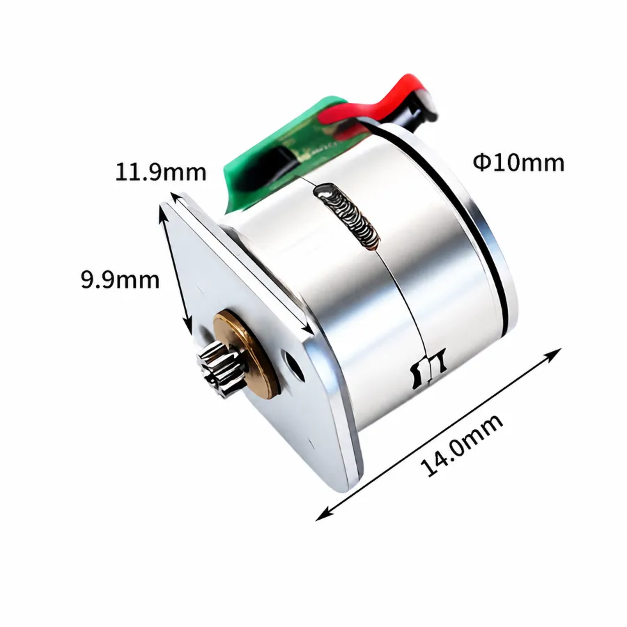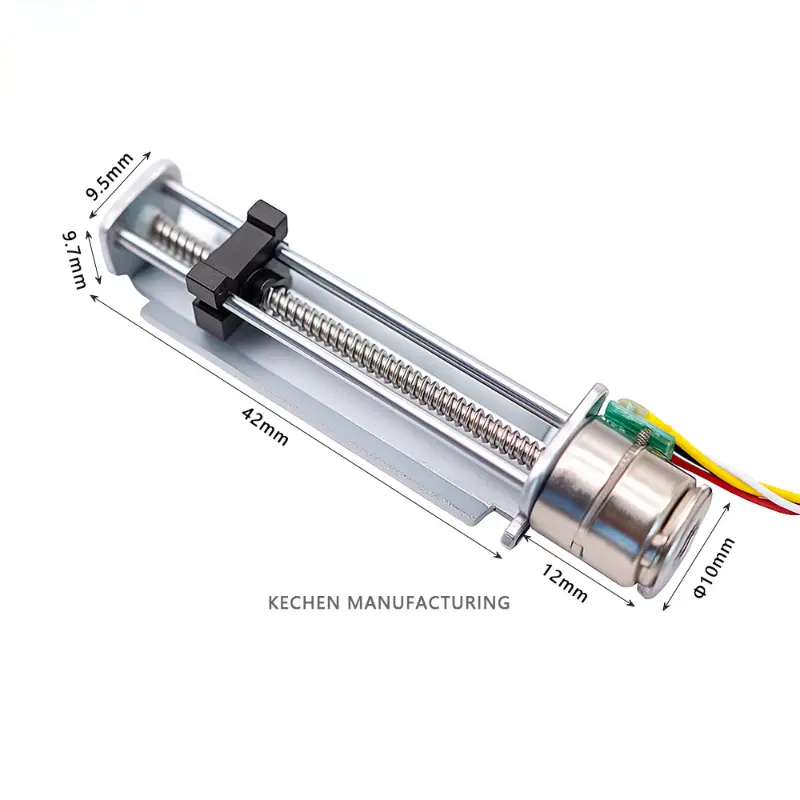
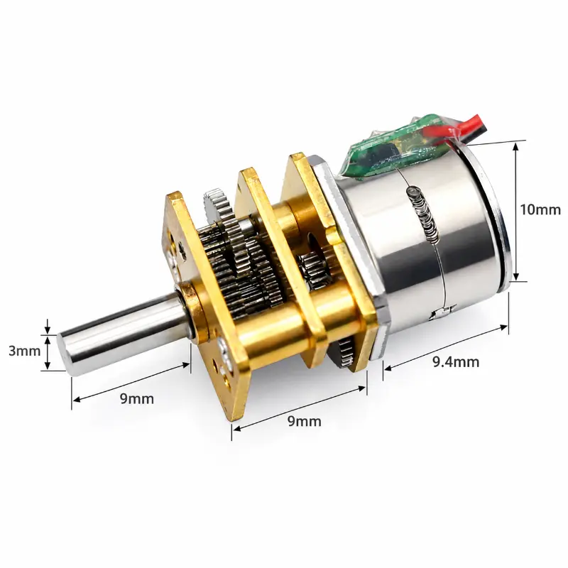
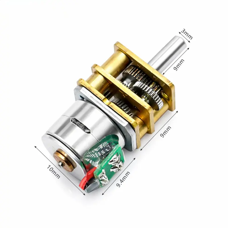
10mm Geared Stepper Motor Series with 3mm D-Shaft and 5V/12V Options
10mm Geared Stepper Motor Technical Specifications
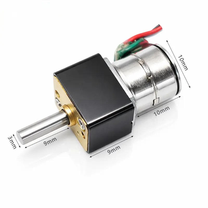
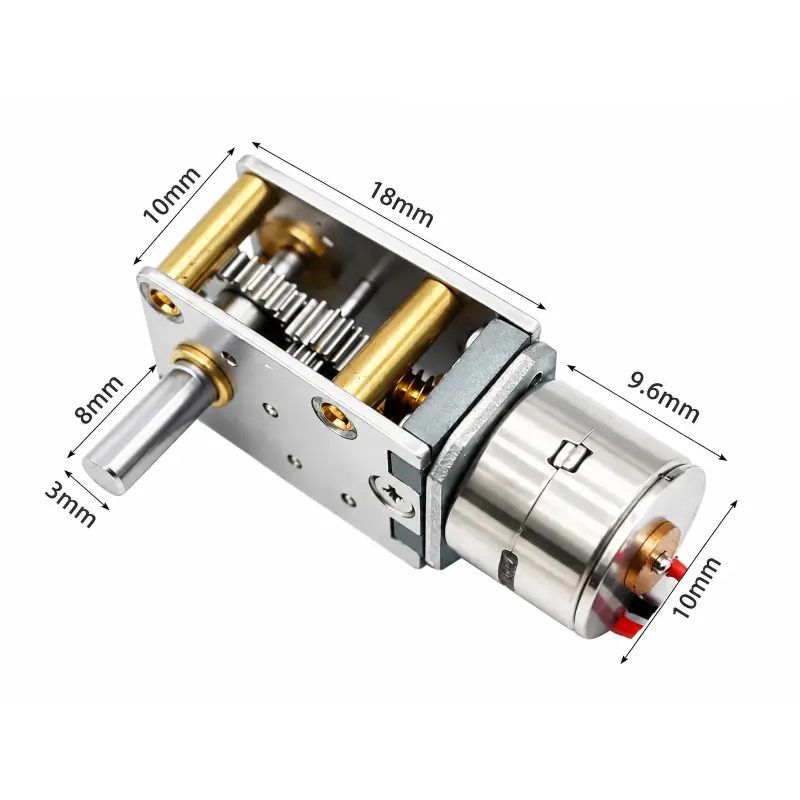
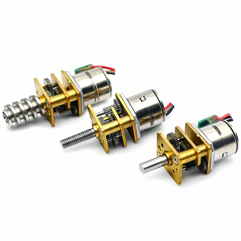
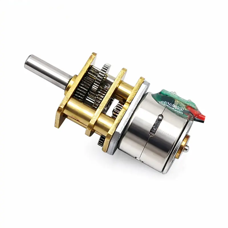
The KC-GM12-10BY is a 10mm geared stepper motor combining a 2-phase permanent magnet stepper motor with a multi-stage spur reduction gearbox. This miniature geared stepper motor is available with different winding configurations, gear ratios and output shaft options for controlled rotary motion in small mechanical assemblies.
Motor and Electrical Specifications
| Parameter | Specification |
|---|---|
| Product Model | KC-GM12-10BY |
| Brand | Kechen Motor |
| Manufacturer | Shenzhen Kechen Micro Motor Technology Co., Ltd. |
| Motor Type | 2-phase permanent magnet stepper motor |
| Motor Configuration | 2-phase, 4-wire |
| Motor Diameter | 10 mm |
| Rated Voltage | 5 V DC / 12 V DC |
| Phase Resistance | 10 Ω / 30 Ω / 50 Ω (optional) |
| Motor Step Angle | 18°/step before gear reduction |
| Drive Configuration | 4-wire bipolar stepper connection |
| Connector Model | 51021-1400 |
| Connector Pitch | 1.25 mm |
| Connector Pins | 4 pins |
| Wire Specification | UL1571 AWG30 |
| Wire Length | 30 ± 5 mm |
| Parameter Table Wiring | Red: A+; White: A−; Black: B−; Brown: B+ |
| Drawing Wiring | Black: A−; Brown: A; Red: B−; White: B |
| Connection Diagram | 2-2 phase CW (drawing marking) |
| Final Wire Assignment | Requires confirmation against approved samples |
Electrical Verification: The supplied parameter table and engineering drawing show different wire assignments. Phase identification, polarity and connector pinout must be verified before driver connection. Voltage and winding resistance combinations must also be confirmed for the selected variant.
10mm Geared Stepper Motor Gearbox and Mechanical Specifications
The spur gearbox converts motor rotation into lower-speed output motion. Gear ratio selection affects output stepping resolution, available output torque and mechanical packaging. The listed torque range is configuration dependent and does not represent an individual tested value for every reduction ratio.
| Parameter | Specification |
|---|---|
| Gearbox Type | Multi-stage spur gear reduction |
| Gearbox Size | 12 × 10 mm (standard N20 reference dimensions) |
| Gearbox Configuration | Multiple reduction stages available |
| Gear Ratios | 50:1 / 100:1 / 200:1 / 500:1 |
| Listed Rated Torque | 0.5–2.5 kgf·cm (configuration dependent) |
| Output Shaft | 3 mm D-shaft |
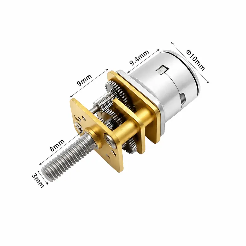
| Optional Shaft | M4 threaded shaft |
| Custom Shaft Length | Available depending on configuration |
| Motor Body Length | 9.4 ± 0.2 mm |
| Gearbox Length | 9 ± 0.1 mm |
| Output Shaft Extension | 9 ± 0.2 mm |
| Shaft Extension Reference | 8.2 ± 0.1 mm (drawing reference) |
| Shaft Diameter | 3.0 mm |
| Mounting Face Width | 10.8 mm (drawing) |
| Mounting Face Height | 12 mm (drawing) |
| Mounting Holes | 2 × M1.6 |
| Hole Center Distance | 9 ± 0.05 mm |
| Hole Diagonal Spacing | 9.4 mm (drawing reference) |
| Mounting Corner Radius | R1 (drawing) |
| Gear Module | 0.5 (drawing reference) |
| Gear Teeth | 12 (drawing reference) |
| Pressure Angle | 20° (drawing reference) |
| Gear Accuracy | JIS grade 5 (drawing reference) |
| Motor Weight | 12 g |
| Drawing Model | KC-10BY25 |
| Drawing Compatibility | Requires confirmation for KC-GM12-10BY |
Specifications are for reference only. Gear dimensions, output shaft geometry and listed torque depend on the selected assembly. Final parameters should be confirmed based on approved samples and project requirements.
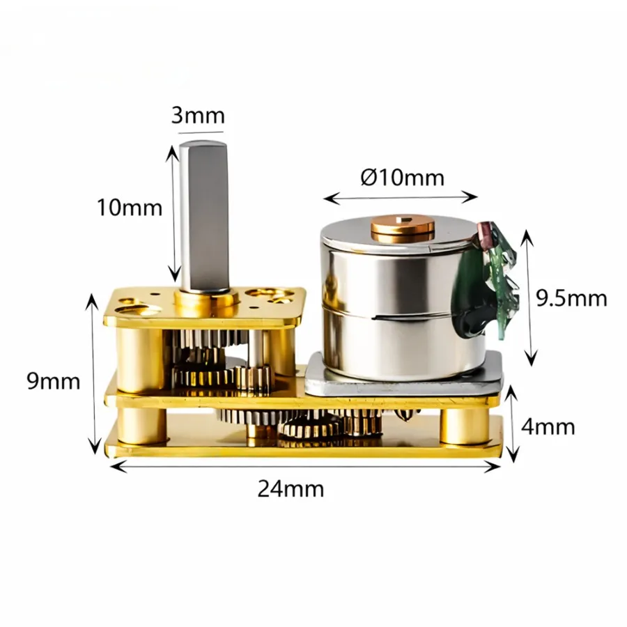
10mm Geared Stepper Motor Dimensions and Mechanical Drawing
Reference dimensions for gearbox mounting, shaft positioning and motor installation. The supplied drawing is marked KC-10BY25; its compatibility with the KC-GM12-10BY D-shaft configuration requires engineering confirmation.
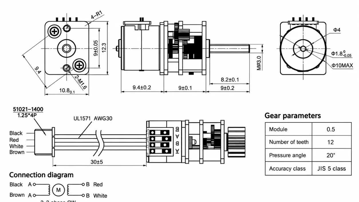
Drawing Verification
The reference drawing includes gear and shaft details that may describe a different output configuration. Confirm the approved mechanical drawing, shaft extension, mounting dimensions and wire assignments before tooling or installation.
10mm Geared Stepper Motor Performance Advantages
- Gear Reduction Control: Multiple spur gear ratios allow output speed and theoretical step resolution to be matched to the motion requirements of the mechanism.
- Electrical Configuration Options: Different voltage and winding resistance options support integration with compatible bipolar stepper drivers.
- Mechanical Installation: The small geared stepper motor uses a defined gearbox mounting interface that can be evaluated during fixture and housing design.
- Output Shaft Selection: D-shaft and threaded shaft configurations provide different coupling arrangements for mechanical assemblies.
- OEM Configuration Support: Gear ratio, winding specification and shaft extension can be reviewed together against application load, positioning and installation requirements.
Motor Selection and OEM Customization
When selecting a micro geared stepper motor, gearbox ratio alone does not determine usable output torque. Motor winding characteristics, driver conditions, operating speed, gearbox efficiency and load duty cycle must be evaluated together.
Configuration Requirements
For an OEM quotation or sample evaluation, provide the required operating voltage, gearbox output speed, load torque, output shaft dimensions, mounting requirements, duty cycle and estimated order quantity. Kechen Motor can review the requested configuration against available manufacturing options.
Payment and Shipping
Payment
- T/T Payment: Bank transfer terms are confirmed through the quotation or proforma invoice before production.
- Sample Payment: Sample charges and payment arrangements are confirmed according to the requested motor configuration.
Shipping
- Air Shipment: Air freight or courier arrangements can be evaluated for samples and smaller consignments.
- Sea Shipment: Sea freight can be considered for production orders according to shipment volume and destination.
- Delivery Schedule: Production lead time, dispatch arrangements and transit estimates are confirmed for each order.
10mm Geared Stepper Motor Frequently Asked Questions
Q1. What Is the Difference Between the 5 V and 12 V Versions?
The 5v dc stepper motor and 12v dc stepper motor options require the appropriate winding and driver configuration. The available phase resistance must be matched to the selected voltage version. Final electrical specifications should be verified against the approved sample.
Q2. How Does the Gear Ratio Affect Output Step Resolution?
The nominal output step angle is calculated by dividing the motor step angle by the gearbox reduction ratio. Higher ratios reduce theoretical angular movement per motor step, but actual positioning accuracy also depends on gearbox backlash and mechanical loading.
Q3. Is the Listed Torque Available With Every Gear Ratio?
No. The stated torque range varies with gearbox ratio, winding configuration and operating conditions. Continuous usable output torque must be confirmed through configuration-specific data and sample validation.
Q4. Can the Output Shaft Be Customized?
The 3 mm D-shaft is the listed output configuration, while an M4 threaded shaft is an option. Shaft extension changes depend on mechanical feasibility and the selected gearbox assembly.
Q5. Which Stepper Driver Is Required?
The motor uses a 2-phase, 4-wire bipolar connection. Driver selection must account for the confirmed winding resistance, operating voltage, phase current and stepping requirements. The final wire-color assignment must be verified because the supplied technical documents differ.
Q6. Can the Mechanical Drawing Be Used Directly for Production?
The drawing should be treated as a reference until its compatibility with the selected KC-GM12-10BY variant is established. Mounting dimensions, shaft details and tolerances require confirmation through an approved drawing.
Q7. Is This Small Stepper Motor With Gearbox Suitable for OEM Assemblies?
The KC-GM12-10BY can be evaluated for small rotary mechanisms requiring geared stepper control. Suitability depends on the available installation space, required output torque, backlash tolerance, operating speed and duty cycle.
Related Motor Specifications
10mm geared stepper motor | miniature geared stepper motor | geared stepper motor | small geared stepper motor | micro geared stepper motor | 12v dc stepper motor | 5v dc stepper motor | 12v stepper motor | small size stepper motor | small stepper motor with gearbox | 3mm D-shaft stepper motor | 2-phase PM stepper motor | 4-wire bipolar stepper motor | 12 × 10 mm spur gearbox | 50:1 to 500:1 gear reduction | M4 threaded shaft option | 2 × M1.6 mounting holes | KC-GM12-10BY | Kechen Motor