

Micro Motor Blogs
N10 Motor Specifications: Avoid Common Selection Mistakes
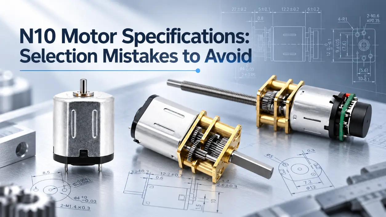
N10 motor specifications should be evaluated as a connected set of electrical and mechanical operating conditions, not as isolated numbers on a datasheet. Selecting a motor only because it has a suitable voltage or the highest listed RPM can result in insufficient loaded speed, excessive current, inadequate torque, or an unsuitable gearbox ratio. Two N10 motors with similar external dimensions can use different windings and produce different speed, current, and torque characteristics. For engineers and purchasing teams, the useful question is therefore not simply “What are the numbers?” but “What do these numbers mean at the required operating point?”
N10 is commonly used as a commercial size or series designation for miniature brushed DC motors. It should not be treated as an IEC, NEMA, or other universal electrical standard. N10 motor specifications can therefore vary by manufacturer and individual motor model. Voltage, current, motor shaft speed, output speed, torque, power, gearbox ratio, duty cycle, and mechanical dimensions need to be reviewed together before a motor is matched to an application.
What Do N10 Motor Specifications Actually Tell You?
N10 motor specifications describe defined electrical and mechanical operating points. They allow several motor variants to be compared, but only when the meaning of each parameter is understood. A speed value without a corresponding load condition, for example, does not show whether the motor can maintain that speed while driving a real mechanism.
When reviewing n10 motor specs, the main values normally include rated voltage, no-load speed, loaded or rated speed, no-load current, rated current, stall current, rated torque, stall torque, mechanical output power, and gearbox ratio when a reducer is fitted. These parameters are related. As mechanical load rises, a brushed DC motor generally requires more torque, draws more current, and operates at a lower speed. Once a gearbox is added, motor shaft speed and gearbox output speed must also be distinguished.
| Parameter | Engineering Meaning | How to Use It |
|---|---|---|
| Rated Voltage | Nominal supply condition specified for the winding | Match the motor winding to the electrical system |
| No-Load Speed | Speed with minimal external mechanical load | Use as a reference, not as expected working speed |
| Rated or Loaded Speed | Speed at a manufacturer-defined load point | Compare with the required operating speed |
| No-Load Current | Current required to overcome internal losses with little external load | Useful for checking baseline current consumption |
| Rated Current | Current at a specified operating point | Compare with driver and power-supply capacity |
| Stall Current | Current at zero shaft speed under the stated test voltage | Check peak-current and protection requirements |
| Rated Torque | Torque at the specified rated operating point | Use with speed, current, duty cycle, and thermal limits |
| Stall Torque | Torque at zero speed under specified electrical conditions | Treat as a boundary condition, not normal working torque |
| Gear Ratio | Reduction between the motor and gearbox output | Use to match output speed and available torque |
A specification table is therefore only the first step. N10 motor specifications become useful when every value is connected to the actual load, required motion, available power source, and mechanical installation.
Why Can N10 Motor Specifications Show Different RPM Values?
N10 motor rpm can vary substantially between motors that look similar from the outside. The main causes include winding design, applied voltage, motor speed constant, magnetic design, brush voltage drop, internal mechanical losses, and the operating load point. These factors affect the bare motor shaft speed before any gearbox reduction is considered.
This distinction is important when comparing N10 motor specifications. A bare motor may operate at several thousand revolutions per minute, while an N10 gearmotor using the same or a similar motor can have an output speed of only tens or hundreds of revolutions per minute. The gearbox has not changed the motor’s original no-load speed specification; it has changed the speed available at the gearbox output shaft.
No-Load RPM vs. Loaded RPM
No-load speed is measured with very little external mechanical resistance. It indicates the motor’s speed characteristics under a lightly loaded condition, but it should not be used as the expected operating speed of a product.
When a load is applied, the motor must generate more torque. For a conventional permanent-magnet brushed DC motor, higher required torque generally increases armature current and reduces speed. In a small feed roller, valve actuator, lock mechanism, or dosing assembly, bearing friction, gear friction, seals, springs, and the driven load all move the operating point away from the no-load condition.
For an illustrative calculation, consider a motor shaft operating at 12,000 rpm before reduction. An ideal 100:1 gearbox would produce a theoretical output speed of about 120 rpm. The actual loaded output speed can be lower because the motor itself slows under load and the gearbox introduces friction and other losses. This is why N10 motor specifications should separate motor shaft speed from gearbox output speed.
For selection, the useful value is the speed required at the actual output shaft under the expected load, not simply the largest no-load RPM in the table.
N10 Motor Torque: Rated Torque, Starting Requirement, and Stall Torque
N10 motor torque data requires the same operating-point discipline as speed data. Rated torque and stall torque describe different conditions, while the torque required during startup is a system requirement rather than a universal third motor rating.
Rated torque is the torque specified at a manufacturer-defined rated operating point. It should not automatically be interpreted as maximum continuous torque unless the datasheet also defines continuous-duty conditions or thermal limits. Whether a motor can sustain a given torque depends on duty cycle, ambient temperature, winding temperature, ventilation, current, and the thermal path into the surrounding mechanism.
Stall torque is measured at zero shaft speed under specified electrical conditions. At stall, back electromotive force is essentially absent, so current can rise toward the stall-current level. Because winding copper loss increases with the square of current, remaining near stall can create rapid temperature rise. N10 motor specifications that include stall torque should therefore use it as a boundary or protection reference, not as the target working torque.
| Torque Condition | What It Represents | How to Use It |
|---|---|---|
| Rated Torque | Torque at the manufacturer’s specified rated operating point | Review together with speed, current, duty cycle, and thermal conditions |
| Starting Requirement | Torque required to overcome static friction and accelerate the load | Evaluate the complete motor, driver, supply, gearbox, and load system |
| Stall Torque | Torque at zero rotational speed under specified test conditions | Use as a limit condition rather than normal working torque |
Available starting torque can also be affected by driver current limiting, supply-voltage drop, battery internal resistance, wiring resistance, gearbox friction, static friction, and load inertia. For example, a mechanism with a spring-loaded latch may require a short torque peak when movement begins even though its running torque is relatively low. That peak should be treated as part of the application requirement rather than assumed from stall torque alone.
When comparing N10 motor specifications, use the rated operating point as a primary reference, define the required duty cycle, and include a justified margin for startup resistance, friction variation, and load uncertainty. Avoid applying a fixed percentage margin without application data.
N10 Motor 6V vs. N10 Motor 12V: More Than a Supply-Voltage Label
An n10 motor 6v and an n10 motor 12v should not automatically be treated as one identical winding operated at two different voltages. Different rated-voltage versions may use different winding designs and resistance values, which can change current demand, speed behavior, torque characteristics, power, and thermal performance.
The important word is “may.” N10 motor specifications do not provide enough information to assume a particular number of winding turns, wire diameter, or winding resistance unless those values are documented for the exact motor model. A 12 V version should therefore not be described as having a specific winding construction unless the manufacturer’s technical data confirms it.
| Comparison Item | 6V Version | 12V Version | Selection Check |
|---|---|---|---|
| Rated Supply | Designed around the stated 6 V operating condition | Designed around the stated 12 V operating condition | Match the actual motor rating to the system supply |
| Winding | May use a different winding configuration | May use a different winding configuration | Do not assume both versions use the same winding |
| Current | Depends on the exact winding and load | Depends on the exact winding and load | Check rated and peak current |
| Speed and Torque | Model-dependent | Model-dependent | Compare the required operating point, not voltage alone |
| Thermal Behavior | Depends on current and duty cycle | Depends on current and duty cycle | Check operating time and temperature conditions |
KC-N10VA-05430 6V Drawing & Performance Curve
KC-GM12-N10-02501 12V Drawing & Performance Curve
KC-GM1024-N10VA-10001 12V Drawing & Performance Curve
In a battery-powered locking mechanism, for example, the supply voltage may already be fixed by the battery pack and control electronics. In that case, N10 motor specifications should be used to find a winding and gearbox combination compatible with the available voltage, required motion, startup current, and load rather than selecting between 6 V and 12 V by preference.
How Gear Ratio Changes N10 Motor Speed and Torque
A gearbox changes the speed and torque available to the driven mechanism, so the gearbox section of N10 motor specifications should never be read as an extension of bare-motor RPM alone. Motor shaft speed and gearbox output speed are separate values.
In principle, a higher reduction ratio produces a lower output speed and greater torque multiplication. A lower reduction ratio keeps more output speed but provides less torque multiplication. The practical result is always affected by gearbox efficiency and mechanical limits.
The simplified relationships are useful for initial calculations:
These relationships are not guarantees of actual output performance. Gear mesh friction, bearings, lubricant, tooth geometry, manufacturing tolerances, and multiple reduction stages all introduce losses. The motor may also slow as its load increases.
There is another important limit: a higher ratio does not provide unlimited usable torque. The gearbox itself has a permissible load. Gear teeth, output shafts, bearings, and housing structure can impose a torque limit before the theoretical multiplication is reached. N10 motor specifications for a gearmotor should therefore include or be evaluated against the gearbox’s rated or permissible torque where that information is available.
| Reduction Direction | Output Speed | Available Output Torque | Main Engineering Check |
|---|---|---|---|
| Lower Ratio | Higher | Lower multiplication | Confirm sufficient torque under load |
| Medium Ratio | Moderate | Moderate multiplication | Balance speed, torque, efficiency, and size |
| Higher Ratio | Lower | Greater multiplication in principle | Check gearbox allowable torque and mechanical losses |
For a low-speed rotary adjustment mechanism, a higher reduction may be useful because output speed is intentionally reduced. For a small roller drive that must maintain higher throughput, excessive reduction may make the mechanism too slow even if torque is adequate. N10 motor specifications should therefore be matched to the required output motion rather than evaluated by ratio alone.
Should You Choose RPM or Torque First?
Neither parameter should be selected completely independently. A practical approach is to define the mechanical operating point first, then use N10 motor specifications to identify a suitable motor and gearbox combination.
- Define the mechanism and required motion. Identify what must move, over what distance or angle, and at what rate.
- Determine the required output RPM. Calculate speed at the actual driven shaft rather than at the bare motor.
- Estimate operating torque. Include the useful load, bearing friction, gear resistance, seals, springs, and other mechanical forces.
- Define duty cycle and startup conditions. A one-second intermittent movement creates a different thermal condition from continuous operation.
- Allow for realistic load variation. Include uncertainty from friction, tolerances, acceleration, and changing mechanical load.
- Select a preliminary gear ratio. Bring motor speed into the required output range while maintaining adequate torque.
- Confirm rated voltage. Match the winding to the actual power system.
- Check current capability. Compare rated current and expected startup or stall current with the driver’s continuous and peak-current limits.
- Verify mechanical fit. Check motor length, gearbox dimensions, mounting arrangement, shaft diameter, shaft length, and available installation space.
- Validate the operating point. Where load, duty cycle, or startup conditions are uncertain, verify performance using representative sample testing.
This sequence is not the only possible engineering workflow. A battery-powered device may be constrained first by voltage, current, and installation space, while a mechanical actuator may be constrained first by torque and output speed. The purpose of N10 motor specifications is to test those constraints against a real motor operating point.
Common N10 Motor Selection Mistakes to Avoid
1. Selecting by No-Load RPM Alone
No-load RPM is useful for characterizing motor speed, but a mechanism operates under load. Loaded speed is therefore more relevant when matching N10 motor specifications to a real product.
2. Treating Stall Torque as Normal Working Torque
Stall torque occurs at zero speed and high current. It is not a normal continuous operating point. Use rated operating data, duty cycle, and thermal limits when evaluating n10 motor torque for repeated or sustained operation.
3. Assuming Every N10 Motor Has the Same Electrical Characteristics
N10 is not a universal electrical specification. Motors with similar external dimensions can have different rated voltage, winding characteristics, current, speed, torque, shaft design, and gearbox configuration.
4. Selecting a Gearbox by Ratio Alone
Ratio is only one part of the transmission. Output speed, operating torque, efficiency, gearbox permissible torque, backlash where relevant, load, and duty cycle also need to be checked.
5. Assuming 6V and 12V Versions Are Interchangeable
Different voltage versions may use different winding characteristics. Confirm N10 motor specifications for the exact model instead of assuming that changing the supply voltage produces an equivalent operating condition.
6. Ignoring Startup and Peak Current
The driver does not necessarily need to supply stall current indefinitely, but its continuous rating, peak-current capacity, current limiting, protection threshold, supply capability, wiring, and connectors should be compatible with the expected operating and startup conditions.
N10 DC Motor Selection Checklist
Before comparing an n10 dc motor for a new project, check whether the application requirements below are defined. This prevents N10 motor specifications from being compared without a common operating target.
- Rated voltage matches the available power system.
- Required loaded output RPM is defined.
- Required operating torque is known.
- Duty cycle and operating time are defined.
- Startup resistance and load variation have been considered.
- Gear ratio matches the required speed and torque range.
- Gearbox permissible torque has been checked where applicable.
- Rated current is compatible with the driver and power supply.
- Expected startup or stall current has been reviewed against peak-current limits.
- Motor and gearbox dimensions fit the installation envelope.
- Shaft diameter, shaft length, and transmission interface are compatible.
- Performance is validated at the intended operating point where application uncertainty remains.
Choosing the Right N10 Motor for Your Application
The most reliable use of N10 motor specifications is to treat voltage, current, RPM, torque, power, duty cycle, gear ratio, gearbox limits, and mechanical dimensions as one operating system. The highest no-load speed is not automatically the most suitable speed, and the highest stall torque is not automatically the usable working torque.
For procurement comparison, ask suppliers to present N10 motor specifications at clearly identified operating conditions. A useful comparison should distinguish bare motor speed from gearbox output speed, identify the voltage and load condition used for each performance value, and avoid mixing stall data with normal rated operating data.
For an N10 motor recommendation, provide the required voltage, target output RPM, required operating torque, duty cycle, available installation space, shaft requirements, gearbox requirement, driver current limits, and estimated order quantity. If startup load or friction cannot be predicted accurately, representative sample testing provides a more reliable basis than selecting from one maximum number on a datasheet.
In one sentence: N10 motor specifications are most useful when they define the motor’s actual operating point under the electrical, mechanical, and thermal conditions of the application.
FAQ
Is No-Load RPM the Speed an N10 Motor Will Run at in the Final Product?
No. No-load RPM is measured with minimal external mechanical resistance. Bearings, gearbox losses, seals, springs, driven loads, and other sources of resistance require torque, which normally reduces operating speed. For engineering selection, compare the required loaded output speed with rated data or representative test results rather than using no-load RPM alone.
Can Stall Torque Be Used as the Required Continuous Working Torque?
No. Stall torque is measured at zero shaft speed under specified electrical conditions and is associated with high current. Rated torque should also not automatically be called continuous torque unless continuous-duty conditions are defined. For sustained operation, review torque together with current, duty cycle, winding temperature, ambient conditions, and the motor’s thermal limits.
Can a 6V N10 Motor Be Replaced Directly by a 12V N10 Motor?
Not on voltage rating alone. An n10 motor 6v and an n10 motor 12v may use different winding characteristics and can have different current, speed, torque, and thermal behavior. Compare the exact N10 motor specifications for both models against the power supply, driver limits, required output RPM, load torque, gearbox ratio, and duty cycle before treating them as alternatives.