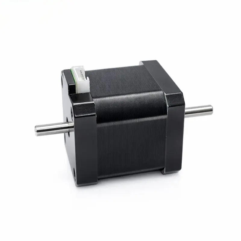
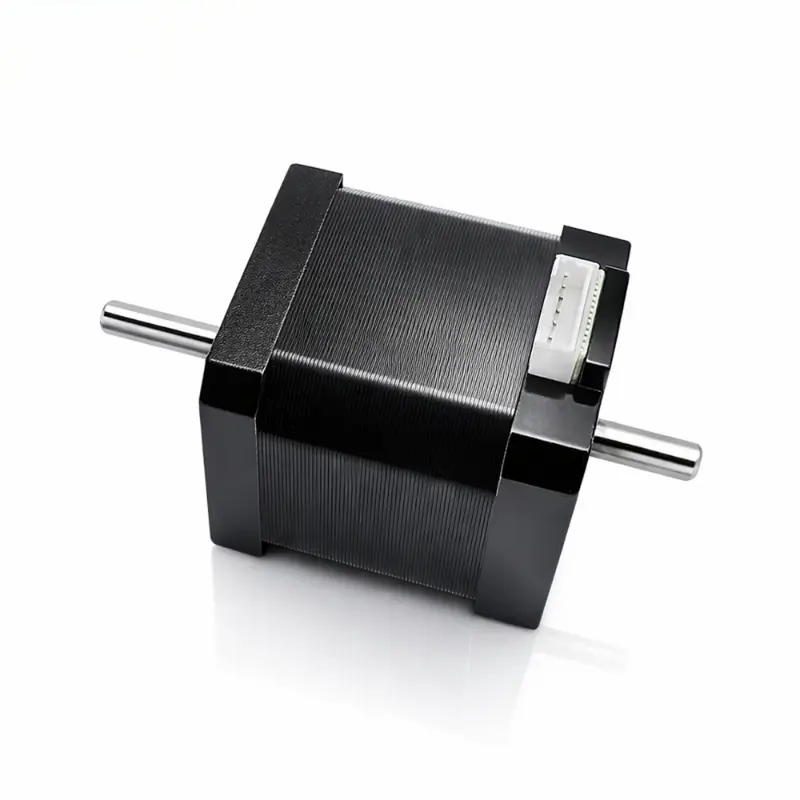
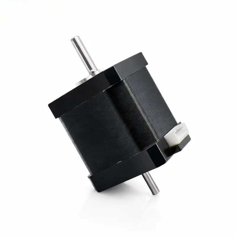
NEMA 17 Dual Shaft Stepper Motor 48mm 1.5A Bipolar Hybrid 2-Phase
Related Product Documents & Downloads
| Document Description | File Details |
|---|---|
| NEMA 17 48mm Dual Shaft Stepper Motor 24V Technical Drawing | PDF · English · 174 KB |
NEMA 17 Dual Shaft Stepper Motor Technical Data
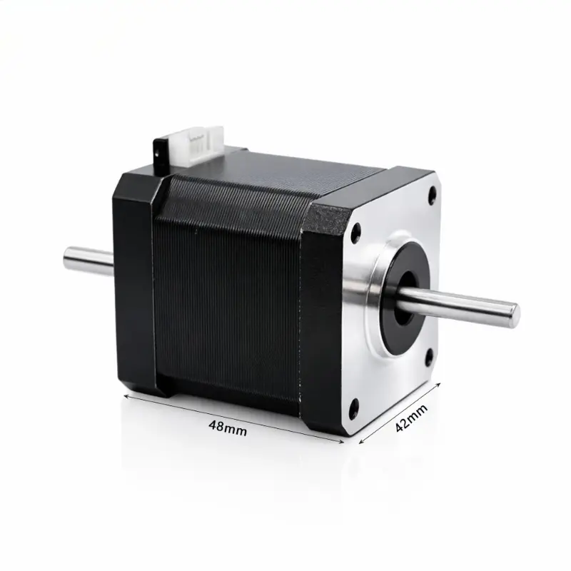
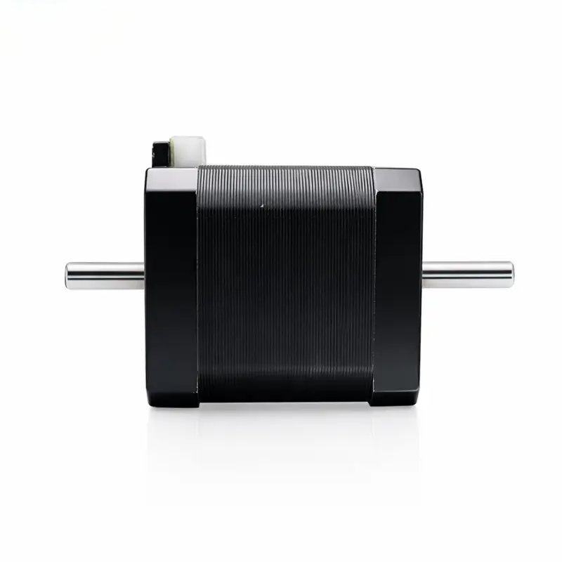
The KC-42HYB48S4 nema 17 dual shaft stepper motor is a 42 mm frame, 48 mm maximum body-length bipolar hybrid stepper designed for motion assemblies requiring shaft access from both sides of the motor. Its two-phase winding, 1.8° step angle and 24 V DC driving configuration support controlled indexing, positioning and transmission integration. The dual-shaft structure can accommodate mechanisms such as hand wheels, secondary couplings, sensing components or synchronized mechanical elements without requiring an additional through-drive arrangement.
NEMA 17 Dual Shaft Stepper Motor Video
KC-42HYB48S4 Electrical And Performance Specifications
| Parameter | Specification |
|---|---|
| Primary Model | KC-42HYB48S4 |
| Product Name | NEMA 17 dual-shaft hybrid stepper motor |
| Motor Type | Bipolar hybrid stepper motor |
| Number Of Phases | 2 phases |
| Step Angle | 1.8° ± 5% |
| Driving Voltage | 24 V DC |
| Rated Voltage | 2.7 V |
| Rated Current Per Phase | 1.5 A |
| Phase Resistance | 1.8 Ω ± 10% |
| Phase Inductance | 3.5 mH ± 20% at 1 kHz, 1 V RMS |
| Holding Torque | ≥ 4 kg·cm |
| Detent Torque | 150 g·cm, reference value |
| Rotor Inertia | 75 g·cm², reference value |
| Dielectric Strength | 500 V AC for 1 min, leakage current ≤ 5 mA |
| Insulation Resistance | 100 MΩ at 500 V DC |
| Insulation Class | Class B, 130 °C |
| Maximum Temperature Rise | 80 K |
| Operating Environment | −10 °C to 55 °C, 20% RH to 90% RH |
| Storage Environment | −20 °C to 65 °C, 15% RH to 90% RH |
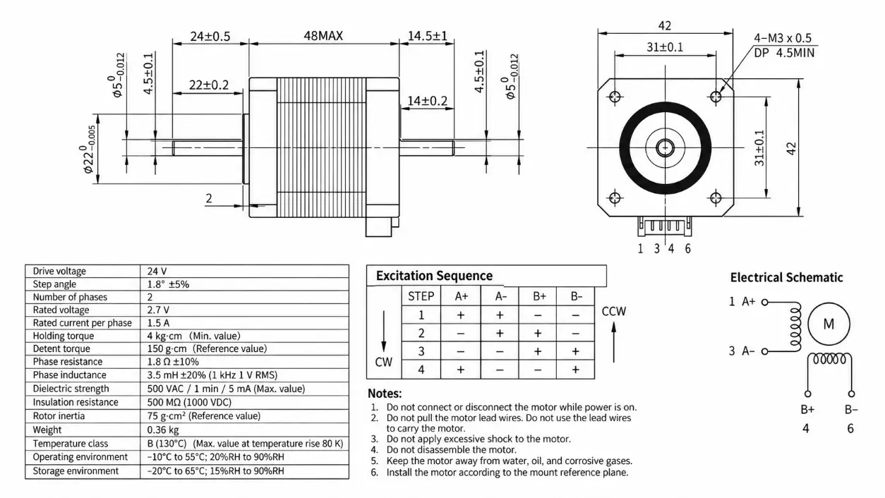
| Winding Connection | A+: Pin 1; A−: Pin 3; B+: Pin 4; B−: Pin 6 |
| Excitation Step 1 | A+ positive, A− positive, B+ negative, B− negative |
| Excitation Step 2 | A+ negative, A− positive, B+ positive, B− negative |
| Excitation Step 3 | A+ negative, A− negative, B+ positive, B− positive |
| Excitation Step 4 | A+ positive, A− negative, B+ negative, B− positive |
Dual-Shaft Integration Characteristics
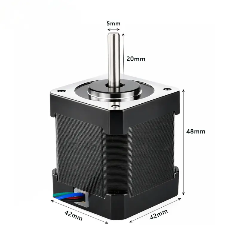
As a nema 17 hybrid stepper motor with a standardized 42 mm square frame, the KC-42HYB48S4 can be evaluated against common NEMA 17 mounting layouts while retaining its specific 31 ± 0.1 mm mounting-hole spacing. The 48 mm body places it in the nema 17 48mm class commonly considered when an engineer needs additional motor length for torque capability but still needs to remain within a 42 mm mounting envelope.
The 5 mm shaft diameter and front-and-rear output configuration distinguish this nema 17 dual shaft design from single-shaft versions. The front shaft can drive the primary mechanical load while the rear shaft can support a handwheel, encoder coupling, damping element or secondary mechanism. For controller selection, the 24v nema 17 stepper motor should be matched with a bipolar driver capable of regulating the specified 1.5 A phase current rather than treating the driving supply voltage as the winding-rated voltage.
Mechanical Dimensions And Related Variant Specifications
| Parameter | Specification |
|---|---|
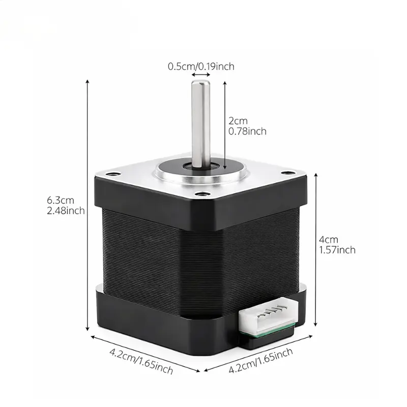
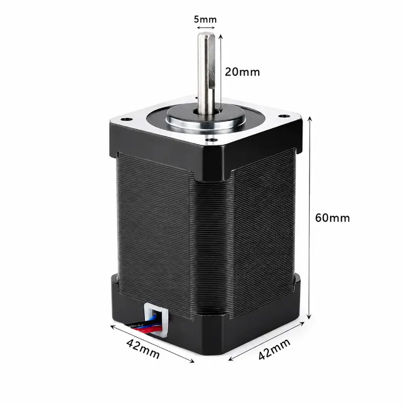
| Motor Frame | 42 mm × 42 mm |
| Motor Body Length | 48 mm max |
| Shaft Diameter | Ø5 mm, tolerance 0 / −0.012 mm |
| Shaft Flat Dimension | 4.5 ± 0.1 mm |
| Rear Shaft Length | 24 ± 0.5 mm |
| Rear Shaft Flat Length | 22 ± 0.2 mm |
| Front Shaft Length | 14.5 ± 1 mm |
| Front Shaft Flat Length | 14 ± 0.2 mm |
| Mounting Hole Spacing | 31 ± 0.1 mm |
| Mounting Holes | 4 × M3 × 0.5 |
| Minimum Thread Depth | 4.5 mm |
| Weight | 0.36 kg |
| Related Model | KC-42HB-48L |
| Related Model Motor Type | Bipolar stepper motor |
| Related Model Size | 42 mm × 42 mm × 48 mm |
| Related Model Driving Voltage | 12 V / 24 V DC |
| Related Model Rated Current | 2 A per phase |
| Related Model Step Angle | 1.8° |
| Related Model Number Of Phases | 2 phases |
| Related Model Phase Resistance | 1.9 Ω |
| Related Model Shaft Diameter | 5 mm |
| Related Model D-Shaft Flat | 4.5 mm |
| Related Model Shaft Length | 20 mm |
| Related Model Holding Torque | 6.8 kg·cm |
| Related Model Number Of Leads | 4 leads |
| Related Model Connection | A+ black, A− green, B+ red, B− blue |
| Related Model Weight | 257 g |
NEMA 17 Dual Shaft Mechanical Drawing
Engineering Advantages
- Dual output shafts provide two mechanical interfaces for drive, sensing, manual adjustment or secondary transmission components.
- The 42 mm bipolar stepper motor frame supports integration into equipment designed around common NEMA 17 mounting envelopes.
- A 1.8° step angle provides 200 full steps per revolution before driver microstepping is applied.
- The 1.5 A phase-current specification provides a defined electrical reference for selecting a compatible current-regulated bipolar driver.
- Specified shaft flats, M3 mounting threads and dimensional tolerances support mechanical fit verification during OEM design review.
- The related KC-42HB-48L offers a higher-current 2 A configuration and 6.8 kg·cm holding-torque reference when another 48 mm NEMA 17 configuration is being evaluated.
Application And Selection Notes
Selection should account for load inertia, acceleration profile, operating speed, driver current setting, thermal conditions and coupling geometry rather than holding torque alone. A nema 17 bipolar stepper motor can lose available torque as stepping frequency increases, so application validation should consider the complete torque-speed requirement. The dual shaft hybrid stepper motor format is particularly useful where the rear shaft serves a functional purpose instead of remaining unused. Engineers comparing a 48mm nema 17 stepper motor should also confirm body clearance, front and rear shaft space, connector orientation and the required mounting-hole pattern before releasing a mechanical assembly.