

Micro Motor Blogs
How to Choose a 180 DC Motor: Voltage, RPM, Torque & Load
Choosing a 180 dc motor from voltage and no-load RPM alone can lead to an incorrect operating point. A motor that reaches the required speed with a free shaft may slow excessively, draw more current, or fail to start after it is connected to the real mechanism. For an engineer or technical buyer, voltage, loaded RPM, torque, current, duty cycle, thermal conditions, shaft geometry, and installation space should therefore be considered together. The term 180 motor describes a commonly used family of small brushed DC motors, but it does not define one universal electrical or mechanical specification.
Dimensions, winding characteristics, rated voltage, speed, current, torque, shaft configuration, and mounting details can vary between manufacturers and individual models. The drawing and performance data for the exact motor should always be checked before design approval. An 180 brushed motor may be used in different electromechanical drive systems when its operating point and mechanical interface match the application.
1. Start With the Required 180 DC Motor Voltage
Available supply voltage is usually one of the first constraints when selecting a 180 dc motor. It is not the only selection parameter, because available mounting space, required torque, target speed, duty cycle, and transmission design may be equally restrictive. Once the supply system is known, however, the motor winding must be compatible with its actual operating voltage range.
Motor Winding and Supply Voltage
Different windings can be designed for different nominal supply conditions. A dc 180 motor intended for a low-voltage battery system may use a different winding from a motor intended for a higher-voltage power source, even when both motors belong to the same general frame family.
The power source also matters. A battery does not necessarily maintain the same terminal voltage throughout its discharge cycle, while a regulated power supply may hold voltage within a narrower range. Wiring resistance, connectors, control electronics, and driver losses can further reduce the voltage that actually reaches the motor during startup.
For example, an actuator may appear electrically compatible with the nominal battery voltage but still have difficulty starting if the supply voltage falls under peak load. The motor should therefore be evaluated using the minimum and maximum voltage expected at its terminals, not only the nominal system voltage.
Voltage, Speed, and Startup Current
For a permanent-magnet brushed DC motor, raising the applied voltage generally increases rotational speed when other conditions remain comparable. During startup or other low-speed conditions, higher applied voltage can also increase current because back electromotive force is low. Under a steady mechanical load, current is primarily associated with the torque demanded by the mechanism.
Operating a winding substantially below its intended voltage can reduce available starting torque. This becomes important when the shaft must overcome seals, gears, belt tension, fluid resistance, or static friction. Operating above the specified voltage range can increase motor speed and electrical or mechanical stress. A search term such as 180 motor dc may locate a product category, but the actual winding specification should determine electrical compatibility.
2. Choose 180 DC Motor RPM From the Actual Operating Speed
A 180 dc motor datasheet may list no-load speed, loaded speed, rated operating data, or other performance points. These values are not interchangeable. No-load RPM is measured with no intended application load on the output shaft, so it should not be treated as the expected speed after the motor is installed.
No-Load Speed vs. Loaded Speed
As mechanical torque demand increases at a fixed supply condition, a typical brushed DC motor slows and draws more current. The useful design value is therefore the speed at or near the intended operating torque.
A small pump provides a practical example. With no impeller load, the motor shaft can rotate at a relatively high speed. Once the impeller begins moving fluid, hydraulic resistance adds continuous torque demand. A fan experiences aerodynamic load, while a gear train introduces tooth-mesh losses, bearing or bushing friction, lubricant drag, and rotating inertia. Each of these changes the motor’s working point.
For engineering evaluation, loaded speed and current measured under a representative mechanism are more useful than a single no-load RPM value. This is especially important when comparing two 180 dc motor variants whose unloaded speeds appear similar.
When Can Higher Motor RPM Be Useful?
Depending on the exact motor specification, an 180 electric motor can be considered for applications such as fans, pumps, rotating mechanisms, tools, or drive systems that use a separate reduction stage. These are application examples rather than guarantees for every 180-series motor.
Higher motor speed may also be useful when a gearbox or external transmission is used to obtain lower output RPM and greater output torque. In that arrangement, motor-shaft RPM and final output-shaft RPM must be treated as separate values.
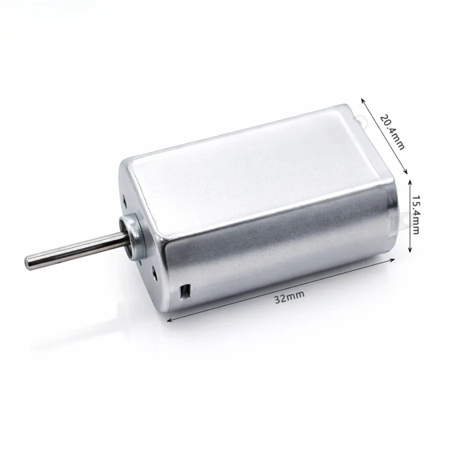
KC-180SH Series 3V–24V 180 DC Motor
A compact permanent-magnet brushed 180 motor series for projects that require different winding voltages and operating speeds. Representative versions cover 3V, 12V, and 24V systems.
- Operating voltage: 3–24V DC
- No-load speed: 6100–15000 rpm
- Body size: 32 × 20.4 × 15.4 mm
- Peak-efficiency torque: 20 g·cm
3. Match Motor Torque to the Mechanical Load
Torque determines whether a 180 dc motor can accelerate and maintain movement in the intended mechanism. It should be reviewed together with current and speed because the operating point of a permanent-magnet brushed motor changes as load torque changes.
Starting Torque, Operating Torque, and Stall Torque
Starting torque describes the torque available while the motor accelerates from rest. For a directly supplied brushed DC motor, initial torque can approach the stall-torque condition because rotational speed and back EMF are initially close to zero. In a real system, driver current limits, battery internal resistance, wiring losses, connector resistance, and supply-voltage drop can reduce the torque actually available during startup.
Operating torque is the torque required at the intended working point after the mechanism has reached its specified operating condition. Stall torque describes the zero-speed condition in which the shaft is prevented from rotating. Ordinary stall torque should not be treated as a continuous operating rating.
For example, a conveyor may need more torque to overcome static friction and accelerate its moving components than it requires after reaching normal speed. A pump may encounter different torque demand as fluid viscosity changes. A reversing gear mechanism can also experience transient torque peaks during direction changes.
An 180 brushed motor should therefore be selected around the normal and transient load profile rather than around stall torque. Operating continuously near stall means low speed, low back EMF, and high current, which produces substantial winding losses.
Account for the Real Mechanical Load
The useful load at the output is only part of the torque that the motor must overcome. Real systems can include bearing friction, seal friction, transmission losses, rotating inertia, gearbox losses, belt tension, radial or axial shaft loads, and changing resistance throughout the duty cycle.
A 180 dc motor that runs freely during bench testing may behave differently after a pinion, coupling, pulley, impeller, or gearbox is installed. Repeated starts, rapid acceleration, and reversing operation can also increase transient torque demand. Representative testing should therefore include the actual transmission and a realistic mechanical load.
4. Understand Load, Current, and Motor Temperature
Torque demand and motor current are closely related in a permanent-magnet brushed DC motor. As the required torque rises, armature current normally rises as well. Higher current increases resistive winding losses, which are strongly influenced by the I²R relationship.
This explains why a motor can produce sufficient short-duration torque but still be unsuitable for continuous operation at the same current level. A short-duration current peak may be acceptable for a particular motor, but the permissible magnitude and duration depend on winding design, thermal limits, ambient conditions, cooling, and operating cycle. A fixed overload duration should not be assumed without data for the exact model.
Continuous high current increases winding losses and can raise brush-system and overall motor temperature. Bearing temperature is influenced by additional factors such as rotational speed, lubrication, radial load, axial load, preload, bearing type, and heat transfer through the housing.
Duty Cycle and Thermal Environment
A dc 180 motor used for short intermittent movements can have different thermal requirements from the same motor operating continuously. Engineers should define the run time, rest time, starting frequency, reversing frequency, enclosure condition, airflow, and ambient temperature before accepting the motor specification.
For example, a motor tested on an open fixture may dissipate heat differently after it is installed inside a plastic enclosure beside a control PCB. Temperature verification should therefore reproduce the final assembly as closely as practical.
5. Check Motor Size, Shaft, and Mechanical Installation
The term 180 motor should not be treated as a substitute for an engineering drawing. Motors sold within the same general family can differ in housing geometry, shaft dimensions, mounting details, winding, terminals, and other features. Mechanical dimensions for the exact model should be verified before tooling or mating parts are released.
Key dimensions include motor body size, total length, shaft diameter, usable shaft length, shaft profile, mounting interface, terminal orientation, and clearance around surrounding components. Depending on the specific design and manufacturer capability, shaft configurations may include round, D-cut, double-flat, extended, or application-specific profiles.
Shaft Tolerance and Coupling Fit
A nominal shaft diameter alone is not sufficient when a pinion or pulley uses an interference fit. Shaft tolerance, mating-bore tolerance, material, insertion process, and required retention should be assessed together. Excessive interference can damage the mating component or overload the shaft during assembly, while insufficient interference can allow the pinion to slip under torque.
Terminal and lead-wire orientation can also determine whether an otherwise compatible motor fits the product. In a restricted housing, terminals can interfere with ribs, covers, PCBs, connectors, or nearby moving parts. Mechanical integration should therefore be reviewed independently from electrical performance.
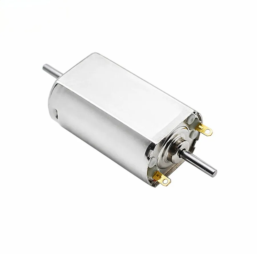
KC-180SH-55L 12V Double Shaft 180 Motor
This 12V 180 motor uses a double output shaft and nickel-plated housing for mechanisms that require mechanical access from both ends of the motor.
- Rated voltage: 12V DC
- Average no-load speed: 9720 rpm
- Double output shaft
- Nickel-plated housing
6. Direct Drive or Gear Reduction?
A direct-drive 180 dc motor can be considered when the application requires motor-level rotational speed without substantial torque multiplication. If the mechanism requires lower output speed and greater output torque, a reduction gearbox or an external transmission may be more appropriate.
| Drive Arrangement | Typical Output Behavior | Engineering Consideration |
|---|---|---|
| Direct motor output | Motor-level speed and torque | Check whether the load can be driven without additional torque multiplication |
| Motor with reduction gearbox | Lower output speed and increased output torque | Include gearbox efficiency, backlash, noise, and output-shaft load |
| Motor with external transmission | Output depends on the selected ratio | Include belt, pulley, gear, or coupling losses and mechanical alignment |
A reduction gearbox decreases output speed while increasing available output torque, subject to efficiency losses. It does not increase mechanical power without limit. Gear-mesh losses, bearing friction, lubricant drag, backlash, and allowable output-shaft load must be included in the drive calculation.
A higher-speed 180 electric motor used with a reduction stage may be preferable to forcing a bare motor to operate continuously at unusually low speed and heavy load. The correct arrangement depends on the required output speed, torque, efficiency, noise, allowable backlash, and installation envelope.
7. Compare 180 Motor Options at the Actual Working Point
Two 180 dc motor versions can have the same nominal voltage and similar no-load RPM while producing different results under load. Winding resistance, motor constants, magnet characteristics, brush design, bearing friction, manufacturing tolerance, and thermal behavior can change the loaded operating point.
| Parameter | What to Verify | Why It Matters |
|---|---|---|
| Supply voltage | Nominal and actual voltage at the motor terminals | Influences speed and startup conditions |
| No-load speed | Reference value from the exact datasheet | Does not represent application speed under load |
| Loaded speed | Speed near the intended operating torque | Shows whether the required working point can be maintained |
| Operating current | Current under representative load | Helps assess electrical demand and winding losses |
| Startup condition | Available current and torque at zero or low speed | Determines whether the mechanism can accelerate reliably |
| Duty cycle | Run, rest, start, and reverse pattern | Changes thermal accumulation |
| Shaft interface | Diameter, tolerance, length, and profile | Determines coupling and assembly compatibility |
| Motor temperature | Temperature in the real housing and load condition | Confirms thermal suitability of the operating point |
For an 180 brushed motor intended for production equipment, sample testing should reproduce the expected power source, mechanical transmission, normal load, peak load, duty cycle, enclosure, and ambient conditions. A single headline RPM value does not provide enough information for a reliable engineering comparison.
8. When Should You Consider a Custom 180 DC Motor?
A standard 180 dc motor may satisfy the nominal voltage requirement but miss the required loaded speed, startup behavior, shaft interface, terminal direction, or installation envelope. In this situation, an OEM-specific configuration can be evaluated if the manufacturer supports the required changes.
Depending on manufacturer capability, changes may include winding specification, target speed, shaft length, shaft profile, lead-wire length, connector type, terminal orientation, rotation direction, and other mechanical interfaces. These options should not be assumed to be available for every 180 motor.
For example, if a press-fit gear and housing have already been released, a different shaft length or profile may be needed to match the existing assembly. Where supported by the manufacturer, a winding change may also be evaluated when the available supply voltage is fixed but the standard motor does not reach the required operating point.
When requesting evaluation of a dc 180 motor, OEM buyers should provide the actual operating requirements rather than only a nominal voltage and free-running RPM.
- Nominal, minimum, and maximum voltage available at the motor
- Required RPM under normal mechanical load
- Operating torque and startup load
- Continuous or intermittent duty cycle
- Available installation dimensions
- Shaft dimensions and coupling method
- Expected ambient and enclosure conditions
- Required lead wire, connector, or terminal arrangement
- Expected production quantity when a manufacturing change is involved
This information allows the motor and application to be evaluated around a defined working point instead of a generic catalogue description.
9. 180 DC Motor Selection Checklist
- Confirm the voltage range available at the motor terminals.
- Define the required RPM under the normal operating load.
- Identify startup, continuous, and peak torque requirements.
- Include friction, transmission losses, inertia, and abnormal load conditions.
- Check operating current at the intended working point.
- Define continuous or intermittent operation and starting frequency.
- Evaluate thermal conditions inside the final assembly.
- Verify motor body, shaft, terminal, and mounting dimensions from the exact drawing.
- Determine whether direct drive, gearbox reduction, or an external transmission is required.
- Test representative samples using the intended power source, transmission, and mechanical load.
The selected 180 dc motor should satisfy electrical, mechanical, and thermal requirements at the same operating point rather than passing each requirement only under separate test conditions.
Conclusion
A suitable 180 dc motor is defined by its ability to maintain the required loaded speed and torque within acceptable electrical, thermal, and mechanical limits in the real application.
FAQ
Can a 180 DC Motor Be Selected Only From No-Load RPM?
No. No-load RPM describes shaft speed without the intended application load. After the motor is coupled to a pump, fan, gear train, pulley, or other mechanism, torque demand increases, motor speed generally falls, and current rises. Two motors with similar no-load RPM can therefore operate at different speeds and currents under the same mechanical load. Loaded-speed data at or near the intended torque provides a more useful comparison.
Can Stall Torque Be Used as Continuous Operating Torque?
No. Ordinary stall torque describes the zero-speed condition where the shaft cannot rotate. Back EMF is then very low, so armature current can become high. Continuous operation close to this condition can create substantial winding losses and motor heating. Stall torque should therefore be treated as a limiting condition unless the exact datasheet explicitly defines a separate continuous torque rating for the intended operating environment.
Does a Higher-Voltage 180 Motor Automatically Provide Better Performance?
No. The motor winding must match the available supply and required operating point. A winding designed for a higher nominal voltage may provide insufficient startup torque if it is operated from a substantially lower supply voltage. Conversely, applying excessive voltage to a lower-voltage winding can raise motor speed and increase electrical or mechanical stress. Voltage should therefore be selected together with loaded RPM, torque, current, duty cycle, and the specification of the exact motor.