

Micro Motor Blogs
130 DC Motor Guide: Size, Specifications, Voltage, Speed, and Applications
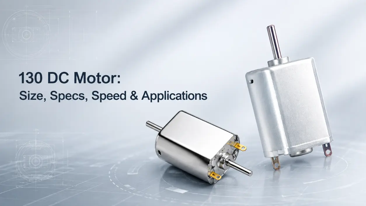
A 130 dc motor may look simple on a drawing, yet selecting one by housing appearance or no-load RPM alone can create problems once the motor is installed. Motors sold under the 130-size designation can differ in winding resistance, operating voltage, current, loaded speed, shaft geometry, brush system, and torque characteristics. For an engineer or purchasing team, the useful question is not whether two motors look alike, but whether the candidate motor reaches the required operating point within the mechanical, electrical, and thermal limits of the product. This guide explains the dimensions, electrical specifications, voltage, speed, torque, load behavior, and application factors that should be checked before a 130 motor is approved.
What Is a 130 DC Motor?
The conventional 130 dc motor discussed in this guide is a small permanent-magnet brushed DC motor associated with the commonly used 130-size designation. The term 130 motor is better understood as a size or frame-family reference than as a universal dimensional or electrical standard. It does not define one fixed voltage, shaft length, speed, current, or torque value.
In a typical 130 brushed motor, the rotor carries the armature winding, permanent magnets create the stator magnetic field, and brushes conduct current through the commutator. Rotation is transferred through the output shaft to the driven component. Depending on the mechanism, that component may be a gear, pulley, fan impeller, eccentric cam, wheel, or coupling.
This distinction matters because two motors with nearly identical external dimensions may use different winding specifications. Differences in winding resistance and electrical design can produce different current, speed, and torque characteristics even when the housing remains similar. Bearing or bushing construction, terminal layout, brush material, and shaft geometry may also differ by series. A 130 electric motor should therefore be identified from its dimensional drawing and performance data rather than from the 130 designation alone.
130 DC Motor Size and Mechanical Dimensions
The mechanical envelope of a 130 dc motor is one of the first checks in an engineering review. The 130 motor size is widely recognized in small DC motor sourcing, but manufacturers do not necessarily use identical dimensions. Housing length, body cross-section, shaft extension, terminal position, front bushing geometry, and mounting details should all be checked against the actual drawing.
Typical 130 Motor Size
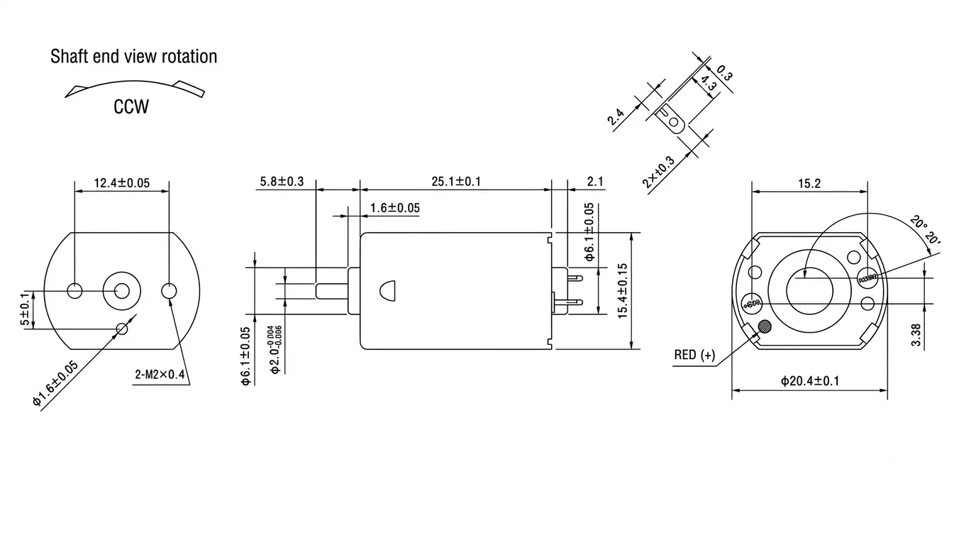
Many 130-size brushed DC motors have a compact body around 25 mm in length with a cross-section near 20 × 15 mm. These figures are useful as a general size-family reference rather than a guaranteed dimension for every 130 size motor. Exact measurements can vary according to the motor series, winding configuration, end-cap construction, shaft design, and application requirements.
| Mechanical Item | What to Check | Possible Integration Issue |
|---|---|---|
| Motor body | Length, width, height | Interference with enclosure, ribs, PCB, or adjacent parts |
| Shaft | Diameter, extension, end geometry | Incorrect gear fit, coupling depth, or axial position |
| Front structure | Bushing, bearing area, mounting face | Misalignment with gearbox or molded support |
| Terminals | Location, direction, spacing | Lead-wire or PCB clearance problems |
| Mounting features | Slots, tabs, holes, support surfaces | Motor movement or incompatible installation |
A 130 size dc motor can also differ in shaft length or end geometry even when the body envelope appears compatible. Depending on the motor series or OEM specification, the shaft may differ in diameter, extension, end shape, or surface treatment. These variations should not be assumed to be standard features of every 130 model.
Why Small Dimensional Differences Matter
Mechanical tolerances directly affect how the 130 dc motor interacts with the driven system. Consider a spur gear pressed onto the output shaft. If the shaft extension is too short, gear-face engagement may be reduced. If the shaft is too long, the gear or shaft end may contact the enclosure or another component. A pulley located at the wrong axial position can also affect belt alignment and add unwanted radial loading.
This is particularly relevant when replacing an existing 130-size motor. A replacement should be checked against the original mounting cavity, gear position, terminal clearance, and shaft engagement. For a new product, reviewing the motor drawing before tooling is released reduces the risk of changing molded components later. Electrical compatibility does not compensate for a mechanical interface that is out of position.
Key 130 DC Motor Specifications
The specifications of a 130 dc motor should be reviewed as a group because voltage, current, speed, torque, and temperature are linked. A high no-load speed is not useful if the motor cannot maintain sufficient speed under the intended load, and a high stall torque figure does not mean the motor is suitable for continuous operation near stall.
| Parameter | Engineering Meaning | Selection Use |
|---|---|---|
| Rated or nominal voltage | Manufacturer-defined operating voltage or reference voltage | Match the motor winding to the actual supply |
| No-load speed | Shaft speed with minimal external load | Reference point for the speed-torque curve |
| Loaded or rated speed | Speed at a defined mechanical operating point | More relevant to actual mechanism speed |
| No-load current | Current required to overcome internal losses at minimal load | Useful for checking baseline electrical behavior |
| Load or rated current | Current at a defined operating condition | Important for power-supply and driver sizing |
| Stall current | Current when the shaft is prevented from rotating | Important for startup, jam, and protection analysis |
| Load torque | Torque specified at a defined operating point | Used to compare the motor with the required working load |
| Stall torque | Torque at zero shaft speed under stall conditions | A boundary value, not a normal continuous operating target |
No-Load Speed Is Not Operating Speed
A 130 dc motor normally reaches its highest shaft speed when external torque is low. Once a fan, gear train, pump mechanism, or other load is attached, shaft speed decreases as required torque increases. The useful value for product design is therefore the speed at the expected working load, not simply the RPM measured with the shaft spinning freely.
For example, a lightly loaded fan mechanism may operate closer to the upper part of the motor speed range. In some geared lock mechanisms, torque demand may rise as a latch or gearbox approaches a mechanical end position. The second application can draw substantially more current even when both products use motors from the same general size family. The load profile must be considered together with the motor curve.
Torque, Current, and Thermal Load
For a permanent-magnet brushed DC motor, electromagnetic torque is closely related to armature current within the normal operating region. As the mechanical load rises, the motor requires more current to produce more torque. If the shaft is forced toward stall, rotational speed approaches zero while current approaches the motor’s stall-current condition.
This relationship should be considered when evaluating a high torque 130 motor. Higher torque at a given operating point may require different winding resistance, higher permissible current, a different magnetic design, or a combination of these factors. The motor cannot be evaluated separately from the power supply, control circuit, wire size, gearbox, and thermal environment.
Copper loss in the winding is approximately proportional to I²R. For example, if current rises substantially because a gear train is overloaded, winding losses increase faster than the current itself. Prolonged overload can therefore produce a significant winding-temperature rise, especially when the motor is enclosed and heat dissipation is limited. A 130 dc motor should be selected around the intended operating point rather than treated as a device that can run continuously near stall torque.
Pcopper = winding copper loss, I = armature current, and R = winding resistance. Because current is squared, a relatively small increase in current can produce a much larger increase in winding loss.
130 DC Motor Voltage and 12V Selection
The 130-size designation does not determine the operating voltage of a 130 dc motor. Motors with similar housings can use different winding specifications and can therefore have different intended voltage ranges. A voltage value should always be taken from the data for the specific model rather than inferred from housing dimensions.
Applied voltage affects motor speed and current behavior. Increasing voltage above the intended operating range can raise shaft speed and can increase electrical and mechanical stress, particularly during startup or heavy loading. Depending on the degree of overvoltage and the duty cycle, winding temperature, brush arcing, commutator wear, and rotational stress can also increase.
How to Interpret 130 DC Motor 12V Searches
The search term 130 dc motor 12v should be interpreted as a request for a 130-size motor specifically designed for operation at or around a manufacturer-defined 12 V operating point. It should not be interpreted to mean that all 130 motors are 12 V motors. Some 130-size brushed DC motors are designed for lower operating voltages, while others may use winding specifications intended for higher voltage systems.
In practice, engineers should check more than nominal voltage. A battery-powered product may experience a higher voltage when fully charged and a lower voltage near the end of discharge. The motor should be reviewed across that expected supply range. The same principle applies to regulated electronic systems in which startup current may cause a temporary supply drop.
A lower-voltage motor may rotate when connected to 12 V, but rotation alone does not demonstrate suitability. The resulting RPM, current, brush condition, winding temperature, and mechanical speed can fall outside the intended limits. For a 130 dc motor, the voltage rating should therefore be checked together with loaded speed, load current, stall current, and duty cycle.
Speed, Torque, and Load Characteristics
The usable performance of a 130 dc motor is defined by its operating point on the speed-torque curve. At low shaft load, speed is relatively high and current is relatively low. As load torque increases, shaft speed normally decreases and armature current increases. This behavior explains why the fastest motor on a product table is not necessarily the most suitable motor for the final assembly.
Consider a hypothetical comparison. Motor A has a no-load speed of 18,000 RPM, while Motor B has a no-load speed of 12,000 RPM. If Motor A loses speed rapidly as load increases, but Motor B maintains a higher speed at the required torque, Motor B may deliver the more suitable operating point. A specification comparison based only on no-load RPM would miss this difference.
Using a Gearbox to Change Output Speed and Torque
A high-speed 130 dc motor can be used in a lower-speed mechanism when the gearbox and motor are correctly matched. In first-order calculations, output speed is approximately the motor speed divided by the gear ratio. Output torque increases with reduction ratio but is reduced by mechanical losses in the gearbox.
n = rotational speed, T = torque, i = reduction ratio, and η = gearbox efficiency. These equations are useful for preliminary sizing; final selection should use measured motor and gearbox performance data.
For example, a motor operating at 10,000 RPM connected to a 50:1 reduction has a theoretical output speed of approximately 200 RPM. Actual system design must also account for gearbox efficiency, allowable gearbox torque, backlash, noise, radial loading, and service conditions. The calculation is useful for initial sizing but does not replace loaded testing.
Direct drive is more appropriate when the required shaft speed is high and the load torque is within the motor’s working range. Fans and some lightweight rotating mechanisms can fit this arrangement. A reduction drive is more appropriate when the output requires lower speed and higher torque, as in many small geared mechanisms.
Where 130-Size DC Motors Are Used
The application of a 130 dc motor depends on its winding, shaft configuration, operating point, gearbox, and duty cycle. The 130 designation alone does not qualify the motor for a specific product. Depending on the actual specification, 130-size motors can be used in compact fans, pumps, small geared mechanisms, locks, personal-care equipment, dispensing systems, electromechanical modules, and other compact drive assemblies.
A micro 130 dc motor used in a light direct-drive mechanism has different requirements from the same size family connected to a gearbox. In a diaphragm-pump drive, for example, an eccentric mechanism can convert shaft rotation into reciprocating diaphragm movement. If a 130-size motor is selected for this structure, motor current can rise as pump pressure and mechanical load increase. The supplier’s motor data should therefore be checked at the intended pump operating point.
In a geared lock mechanism, the motor may operate intermittently rather than continuously. Depending on the latch and gear geometry, torque demand may increase near a mechanical stop. Startup current, transient torque, gearbox ratio, and actuation time may therefore be more important than the highest free-running RPM.
130 Motor Naming and Specification
The term 130 motor identifies a general compact motor size family rather than a complete technical specification. Motors with similar external dimensions can still differ in voltage, winding resistance, loaded speed, current, torque, shaft dimensions, terminal configuration, and mounting details.
For engineering selection, a 130 dc motor should therefore be evaluated by its dimensional drawing and operating data rather than by the 130 designation alone. This approach is especially important when sourcing replacement motors or developing an OEM mechanism where shaft position, electrical load, and installation space must remain consistent.
Brushed Motor Control in Actual Equipment
For a conventional permanent-magnet 130 brushed motor, changing the terminal polarity normally reverses the direction of rotation. Speed can also be controlled using an appropriate PWM drive circuit. In an actual product, PWM frequency, current capability, electrical noise, motor inductance, switching losses, and control requirements should be considered before the drive method is finalized.
How to Select the Right 130 DC Motor
Selection of a 130 dc motor should start from the load and the mechanical envelope rather than from a single catalog parameter. The following sequence provides a practical basis for engineering review and supplier comparison.
- Confirm the available installation envelope, including motor body clearance, terminal direction, mounting support, and required 130 motor size.
- Define the actual supply range rather than stating only the nominal system voltage.
- Specify the required shaft or gearbox output speed under load.
- Estimate working torque, including friction, acceleration, pressure, spring force, or other resistance created by the mechanism.
- Compare load current, startup current, and stall current with the capability of the power source and driver.
- Check shaft diameter, extension, end geometry, gear engagement, and coupling position against the mechanical drawing.
- Determine whether the mechanism should use direct drive or a reduction gearbox.
- Review operating duration, duty cycle, ambient temperature, enclosure conditions, and available heat dissipation.
- Test engineering samples in the actual assembly under representative voltage and load conditions before freezing the production specification.
These checks also explain why the terms 130 motor and 130 size motor should not be used as complete purchasing specifications. Two suppliers may offer motors that fit a similar housing envelope while providing different loaded speed or current characteristics. Small shaft differences can also require changes to a gear, coupling, or molded support. Procurement comparison should therefore use drawings and defined operating-point data rather than a motor-family name alone.
OEM Specification Considerations
An OEM project may require a 130 dc motor that differs from a catalog configuration, but available modifications depend on the manufacturing capability of the selected supplier. Possible specification areas can include winding, target operating speed, shaft dimensions, lead wires, terminals, mounting details, or gearbox matching. These options should be confirmed during engineering review rather than assumed from the motor size designation.
For example, a product may need the same mechanical envelope but a lower loaded speed at a fixed supply voltage. This requirement may lead to a different winding specification, provided that the required torque and thermal limits can still be met. In another design, retaining the motor winding and changing the gearbox ratio may be more appropriate. The correct choice depends on the complete speed, torque, current, noise, efficiency, and space requirements.
When sourcing a 130 dc motor for an OEM assembly, engineers and purchasing teams should provide the operating voltage range, required loaded speed, load or torque information, dimensional limits, shaft requirements, duty cycle, expected quantity, and a clear description of the mechanism. Where performance margins are narrow, current-speed-torque data and temperature testing are more useful than a single headline RPM figure.
Conclusion
The engineering value of a 130 dc motor comes from matching its dimensions, voltage, loaded speed, current, torque, shaft interface, and duty cycle to the real mechanism rather than relying on the 130 designation alone. For OEM sourcing, dimensional drawings, defined operating-point data, and representative sample testing provide a more reliable basis for motor selection than appearance or no-load speed alone.
130 DC Motor FAQ
Are All 130 Motors Mechanically Interchangeable?
No. Motors in the same general size family may differ in body length, body cross-section, shaft diameter, shaft extension, terminal position, mounting structure, and front support geometry. A replacement 130 dc motor should be checked against the complete dimensional drawing. A visually similar housing does not guarantee correct gear engagement, enclosure clearance, or mounting alignment.
Is Every 130 Motor Designed for 12V?
No. The winding and manufacturer-defined operating point determine voltage, not the 130-size designation. A motor designed for a lower voltage may still rotate at 12 V, but that does not make it a suitable 130 dc motor 12v replacement. RPM, current, winding temperature, brush condition, and mechanical limits must be checked at the intended supply voltage.
Does Higher No-Load RPM Mean More Usable Motor Power?
No. No-load RPM describes shaft speed with minimal external torque. Usable output depends on both speed and torque at the required operating point, together with current and thermal limits. A lower-speed 130 dc motor can be more suitable for a loaded mechanism than a faster motor whose speed falls more sharply as torque demand rises.