

Micro Motor Blogs
Overcoming Heat Dissipation and Microstepping Errors in NEMA 8 Stepper Motor Integration
1. Engineering Background of the NEMA 8 stepper motor in Miniature Systems
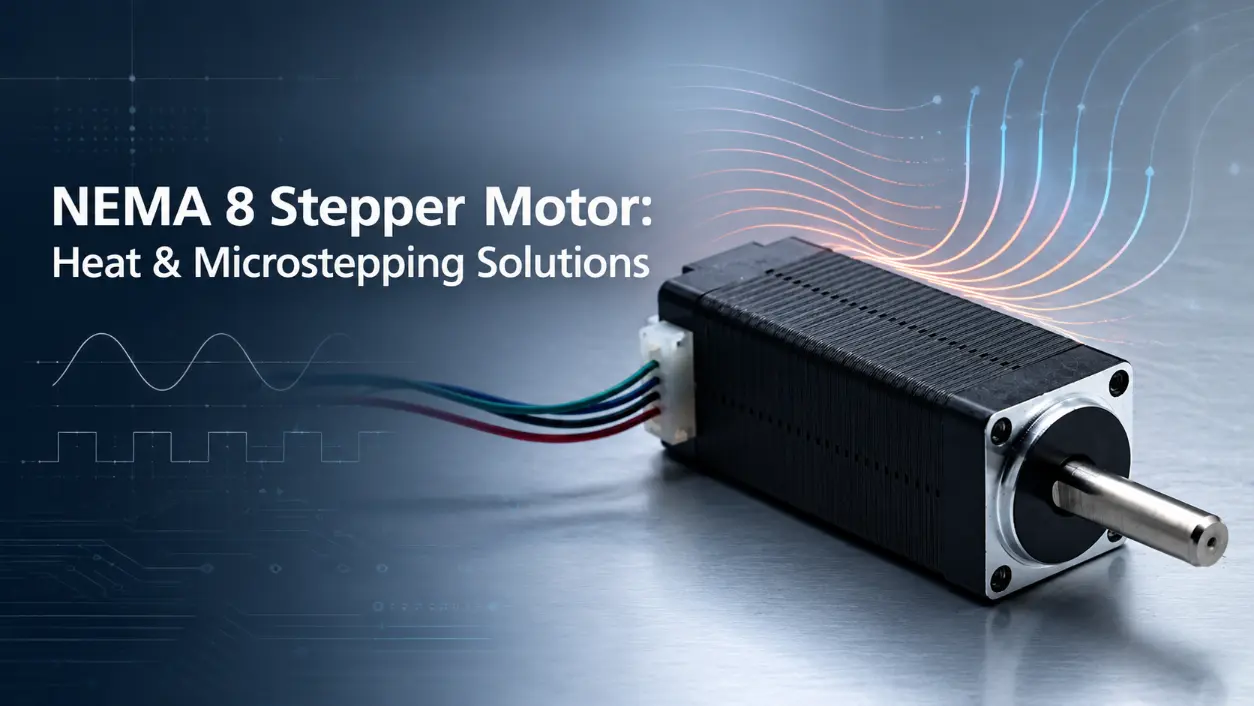
Miniature motion systems deployed in precision medical instruments, optical alignment stages, and micro-fluidic analyzers rely heavily on the NEMA 8 stepper motor to deliver precise incremental positioning within strict space limitations. As design engineers push for higher integration density, managing thermal accumulation and maintaining sub-step accuracy become critical operational bottlenecks. Continuous operation under demanding load profiles often leads to excessive winding temperatures, magnetic saturation, and positional drift, threatening overall system reliability. This engineering guide provides actionable, data-driven solutions to resolve thermal demagnetization, resonance, and microstepping anomalies in high-performance drive architectures, ensuring robust long-term performance across industrial applications.
2. Thermal Limits and Dimensional Constraints of the NEMA 8 stepper motor
Understanding thermal behavior in fractional horsepower actuators requires analyzing both electrical power input and mechanical boundary conditions. When a NEMA 8 stepper motor operates under continuous duty cycles, electrical energy is converted into mechanical work alongside significant resistive losses (I2R). Reviewing the standard NEMA 8 stepper motor dimensions reveals a low-profile 20 mm square frame profile with limited surface area for natural air convection, restricting internal copper mass and conductive thermal paths.
When internal winding temperatures exceed the insulation class threshold (typically Class B at 130°C), permanent neodymium-iron-boron (NdFeB) magnets experience thermal demagnetization. This physical phenomenon directly degrades magnetic flux density, resulting in a measurable drop in holding torque and severe open-loop positioning errors during multi-axis interpolation. The following table outlines typical electrical and thermal parameters for standard miniature configurations:
| Parameter Specification | Standard Rating | Optimized Operating Threshold |
|---|---|---|
| Frame Size (mm) | 20 x 20 | 20 x 20 (Chassis Mounted) |
| Holding Torque (mNm) | 20 – 40 | 25 – 40 (with Thermal Sink) |
| Max Winding Temp (°C) | 130 (Class B) | 60 – 80 (Recommended Range) |
| Phase Resistance (Ω) | 2.5 – 15.0 | Configured for Current Control |
3. Practical Thermal Management Techniques
Mitigating heat accumulation requires precise electrical and mechanical tuning. Driver current optimization serves as the primary software-level intervention. Engineers should configure the motor controller to lower the idle hold current to 30% to 50% of the active run current, significantly reducing Joule heating when the actuator remains stationary. Mechanically, establishing low-resistance thermal conduction paths is vital for continuous operation.
Bolting the motor flange directly to an anodized aluminum chassis or copper mounting plate facilitates conductive heat transfer away from the stator core. For instance, in an automated optical inspection (AOI) gantry, applying a high-conductivity thermal interface material (TIM) between the motor face and the structural bracket effectively lowers thermal resistance. Furthermore, winding temperature rise should be validated using embedded thermocouple sensors near the stator teeth during a standard 4-hour endurance test, ensuring operational stability within safe thermal limits.
Temperature Rise vs. Time (4‑Hour Endurance Test)
▲ Winding temperature profile under continuous duty cycle with thermal management applied.
4. Troubleshooting Microstepping Errors and Resonance
Low-speed resonance and positional drift frequently plague open-loop miniature positioning circuits. When stepping frequencies match the natural frequency of the rotor-load system, severe vibration induces skipped steps and mechanical ringing. To counteract this, engineers must optimize driver configuration parameters, selecting higher microstep resolutions such as 1/16 or 1/32 combined with adaptive mixed-decay modes to smooth current waveforms and suppress harmonic distortion.
When scaling mechanical advantage for specialized applications, choosing the correct integrated variant is crucial. Deploying a nema 8 geared stepper motor multiplies the effective output torque while dividing the step angle, effectively suppressing resonance and improving angular resolution in robotic joint mechanisms and micro-pumps. Alternatively, substituting rotary output with a nema 8 stepper motor with lead screw translates rotational motion into linear displacement with fine pitch precision, minimizing backlash in micro-translation stages used for fiber-optic alignment. Proper tuning of acceleration and deceleration ramps prevents the inertia mismatch between the rotor and the lead screw nut from causing dynamic tracking errors.
Torque‑Speed Characteristic Curve
▲ Holding torque vs. step rate for open‑loop operation with microstepping (1/16) enabled.
5. Implementation Guidelines and OEM Value Proposition
Ensuring long-term reliability in harsh industrial environments demands strict adherence to wiring and grounding protocols. Electromagnetic interference (EMI) generated by high-frequency pulse-width modulation (PWM) switching from the stepper driver can corrupt encoder feedback signals or communication buses. Shielded twisted-pair cables, proper chassis grounding, and ferrite beads on motor leads are standard prerequisites for robust integration.
For original equipment manufacturers (OEMs) developing medical diagnostics, optical instruments, and laboratory automation equipment, sourcing reliable motion components is essential. Factory-direct customization—including tailored stack lengths, specialized winding modifications, and integrated lead configurations—ensures seamless compatibility with specific mechanical constraints. Manufacturers providing stringent quality control protocols, batch consistency, and dedicated application engineering support enable OEMs to accelerate product development cycles while maintaining optimal performance margins across high-volume production runs.
6. Frequently Asked Questions (FAQ)
Systematic thermal management and precise driver parameter optimization ensure reliable, long-term operational accuracy in miniature motion integration.