

Micro Motor Blogs
NEMA 17 Torque: Holding Torque, Running Torque & Selection
NEMA 17 torque is not a fixed value defined by the NEMA 17 frame designation. NEMA 17 identifies a nominal 1.7-inch, approximately 42 mm-class mounting frame, while actual torque depends on the motor’s electromagnetic design, body length, phase current, winding resistance, inductance, driver conditions, operating speed, and mechanical load. For a moving axis, the holding-torque value printed on a datasheet is therefore only one part of the selection process.
Engineers should distinguish static holding capability from torque available during rotation. A motor can maintain a stationary load successfully yet lose synchronization when the same mechanism accelerates or operates at a higher speed. Reliable NEMA 17 torque selection requires the motor, driver, transmission, motion profile, and load to be evaluated as one system.
What Does NEMA 17 Torque Actually Mean?
NEMA 17 Defines a Frame Interface, Not a Torque Rating
NEMA 17 describes the mechanical frame and mounting interface rather than a standardized output torque. Motors using the same nominal frame can have different body lengths, rotor structures, winding configurations, phase-current ratings, resistance values, inductance values, and rotor inertia. These differences directly affect nema 17 stepper motor torque under real operating conditions.
For example, a 34 mm-body motor and a 48 mm-body motor may fit the same mounting pattern but provide different holding torque and different dynamic behavior. A longer motor may contain more active magnetic material, but length alone does not determine usable NEMA 17 torque. Winding design and electrical operating conditions remain important, especially as rotational speed increases.
Two motors with similar external dimensions can also behave differently. If one winding has higher inductance, phase current may rise more slowly at higher stepping rates under the same driver and supply conditions. The motor may still provide adequate static torque but retain less usable torque at the required shaft speed. This is why dimensional compatibility alone does not confirm torque compatibility.
Common Torque Units in NEMA 17 Datasheets
Stepper motor datasheets commonly express torque in N·m, N·cm, kgf·cm, or oz·in. These values should be converted to the same unit before motors are compared. Searches for nema 17 torque nm and nema 17 torque ncm usually refer to the same physical quantity expressed at different scales, while nema 17 torque kg cm is commonly intended to mean kgf·cm.
| Torque Unit | Engineering Conversion |
|---|---|
| 1 N·m | 100 N·cm |
| 1 kgf·cm | Approximately 0.098 N·m |
| 1 N·m | Approximately 10.2 kgf·cm |
As a simple conversion example, 45 N·cm equals 0.45 N·m. A value of 4.2 kgf·cm is approximately 0.41 N·m. The numbers appear different because the units are different, not because one motor necessarily produces substantially more torque.
NEMA 17 Torque and Holding Torque
What Is NEMA 17 Holding Torque?
NEMA 17 holding torque is the maximum torque available at standstill under specified excitation conditions before the motor can no longer maintain the commanded equilibrium position. The rotor is energized but not rotating, so holding torque represents static capability rather than torque during continuous motion.
Holding torque is commonly listed in stepper motor datasheets and product tables. It is useful when a mechanism must remain stationary against an external load. In a valve-positioning assembly, for example, the motor may rotate the valve to a defined angular position and then remain energized. The available holding torque determines whether the motor has sufficient static margin to maintain that commanded position against the valve load.
The important limitation is that nema 17 holding torque cannot be assumed to equal usable NEMA 17 torque during rotation. Once the shaft begins moving, winding inductance, back EMF, driver operation, stepping frequency, acceleration, and mechanical demand change the available operating margin.
Why Holding Torque Is Not Working Torque
Current in a stepper motor winding cannot change instantaneously because the winding is inductive. As stepping frequency rises, less time is available for phase current to approach its commanded value before the next commutation event. Back EMF also increases with motor speed. Under a given driver and supply condition, these effects generally reduce available dynamic torque as speed increases.
For example, suppose a motor is specified at 0.5 N·m holding torque. That value should not be interpreted as evidence that the motor will still provide 0.5 N·m at 600 RPM. Torque at 600 RPM must be determined from suitable dynamic performance data or verified under the intended driver, voltage, current, and load conditions.
This difference becomes visible in belt-driven inspection stages, indexing mechanisms, and automated handling systems. A motor may hold the axis reliably after stopping but lose synchronization during rapid acceleration because the required dynamic torque exceeds the torque available at that operating point.
Where Holding Torque Is Most Relevant
- Vertical positioning stages that remain stationary under load
- Indexing fixtures that pause at defined angular positions
- Clamping and locking mechanisms
- Valve positioning assemblies
- Laboratory handling systems with repeated stop-and-hold cycles
- Mechanisms exposed to external back-driving forces
In a vertical lead-screw axis, sufficient static NEMA 17 torque may help maintain position while energized. However, motor holding torque should not automatically be treated as a substitute for a mechanical brake or a transmission designed to resist back-driving where machine safety requires independent load retention.
NEMA 17 Running Torque During Motion
What Does NEMA 17 Running Torque Refer To?
The term nema 17 running torque is commonly used to describe torque available while the motor is rotating. In technical stepper motor data, dynamic capability is more accurately evaluated from pull-out torque or other speed-dependent torque data at the required operating point.
Unlike holding torque, dynamic NEMA 17 torque is not represented by one universal number. It varies with rotational speed, current regulation, supply conditions, winding characteristics, driver method, temperature, and the motor’s electromagnetic design.
For an indexing conveyor, the motor may maintain the mechanism at rest without difficulty but fail to accelerate the load to the required cycle rate. In that case, the relevant engineering question is not whether the motor has sufficient static holding capability. The relevant question is whether enough torque remains available throughout acceleration and the required running-speed range.
Why Available Torque Changes with Speed
Driver current: Phase current directly affects winding excitation. If the driver is set below the current used for the motor’s published performance data, available torque will generally be lower. Current should also remain within the motor and driver thermal limits.
Supply voltage: A current-regulated stepper driver can use a DC bus voltage that differs from the phase-voltage value calculated from winding resistance and rated current. The phase voltage printed in a motor specification should therefore not automatically be treated as the required system power-supply voltage. Driver voltage limits, current regulation, motor temperature, and application requirements still apply.
Winding inductance: Higher winding inductance can restrict how quickly current reaches its target value as stepping rate rises. The effect is particularly relevant when evaluating NEMA 17 torque at higher operating speeds.
Microstepping: Microstepping can reduce low-speed vibration and provide finer commanded position increments. The incremental torque available around an individual microstep position is lower than the full-step holding value. This should not be interpreted as an equivalent proportional reduction in the motor’s overall rotational torque.
Acceleration and inertia: Load inertia does not continuously consume torque at constant speed. Instead, inertia increases torque demand primarily during acceleration, deceleration, and direction reversal. Mechanical friction, in contrast, consumes part of the available shaft torque whenever frictional forces are present.
Holding Torque vs. Torque During Rotation
| Parameter | Holding Torque | Torque During Rotation |
|---|---|---|
| Shaft condition | Stationary | Rotating |
| Main use | Static position retention | Driving a moving load |
| Speed condition | Zero speed | Speed dependent |
| Common documentation | Frequently listed as a single value | Usually evaluated from dynamic torque data |
| Selection importance | Static load assessment | Motion and acceleration assessment |
For moving machinery, NEMA 17 torque should therefore be checked at the actual operating speed rather than inferred from the zero-speed holding specification.
How Much Torque Does a NEMA 17 Have?
The question how much torque does a nema 17 have has no single numerical answer. NEMA 17 defines the mechanical frame interface, not one electromagnetic design. Nema 17 motor torque can therefore differ substantially between motors that share similar mounting dimensions.
Motor-design factors include body length, stator geometry, rotor geometry, magnet system, winding turns, conductor size, winding resistance, winding inductance, and rated phase current. Operating-condition factors include actual driver current, supply voltage, driver control method, shaft speed, temperature, acceleration, and duty cycle.
A motor with higher holding torque may also have relatively high winding inductance, and its available torque may fall more rapidly with speed under a particular driver and supply condition. This relationship cannot be predicted from body length alone. A longer motor should therefore not automatically be selected simply because a larger static NEMA 17 torque value is listed.
Shaft configuration is another separate issue. A dual-shaft design can provide a rear connection for an encoder, hand wheel, brake, or other mechanism, but the second shaft does not itself increase electromagnetic torque. Mechanical configuration and torque generation should be evaluated independently.
NEMA 17 Torque Selection for Real Applications
Start with Required Load Torque
Nema 17 torque selection should begin with the mechanical load rather than with the largest torque number in a product table. Required shaft torque can include process load, bearing friction, guide friction, transmission losses, gravity, acceleration torque, pulley radius, screw geometry, and external forces.
For a belt-driven axis, required shaft torque is related to the tangential drive force and pulley radius. Increasing pulley radius increases the shaft torque required to produce the same tangential force. Belt pretension should be evaluated separately because excessive pretension can increase radial bearing load, friction, and transmission losses.
For a lead-screw axis, required motor torque depends on axial force, screw lead, mechanical efficiency, preload, guide friction, and acceleration. A larger lead provides more linear travel per revolution but normally requires more input torque for the same axial force when other factors remain comparable.
Maintain an Engineering Torque Margin
A drive system should not normally be sized so that calculated peak load torque equals the motor’s available torque at the same operating point. Manufacturing tolerances, lubricant condition, bearing preload, cable drag, temperature, load variation, transmission wear, and acceleration can change the actual demand.
No single safety-margin percentage is appropriate for every NEMA 17 application. A slowly adjusted optical stage and a high-cycle indexing axis have different acceleration, duty-cycle, thermal, and load-variation requirements. Engineers should identify the most demanding realistic operating condition and verify adequate NEMA 17 torque margin under that condition.
Match Torque to the Required Speed
Static torque does not describe the entire operating range. As a hypothetical example, a motor that performs reliably at 100 RPM may have substantially less available torque if the same system is required to operate at 700 RPM. The exact change cannot be established without the relevant motor and driver performance data.
Before finalizing a motor, define the minimum, nominal, and maximum operating speeds together with acceleration time, deceleration time, start-stop frequency, and required load torque. The available NEMA 17 torque should then be checked across this operating region.
Check Electrical Compatibility
- Rated phase current
- Phase resistance
- Phase inductance
- Driver current range
- Driver control method
- Power-supply voltage
- Microstepping setting
- Motor and driver thermal limits
If a motor’s published torque performance is specified at a phase current substantially above the driver’s limit, a lower-current driver will generally not reproduce that rated torque performance. Increasing rated current on the motor label also does not automatically mean the motor will provide better results in an existing machine.
For equipment with a fixed driver platform, winding characteristics can be as important as motor dimensions. A mechanically compatible motor may still be electrically unsuitable if its current or inductance does not match the intended operating conditions.
Check Mechanical Compatibility
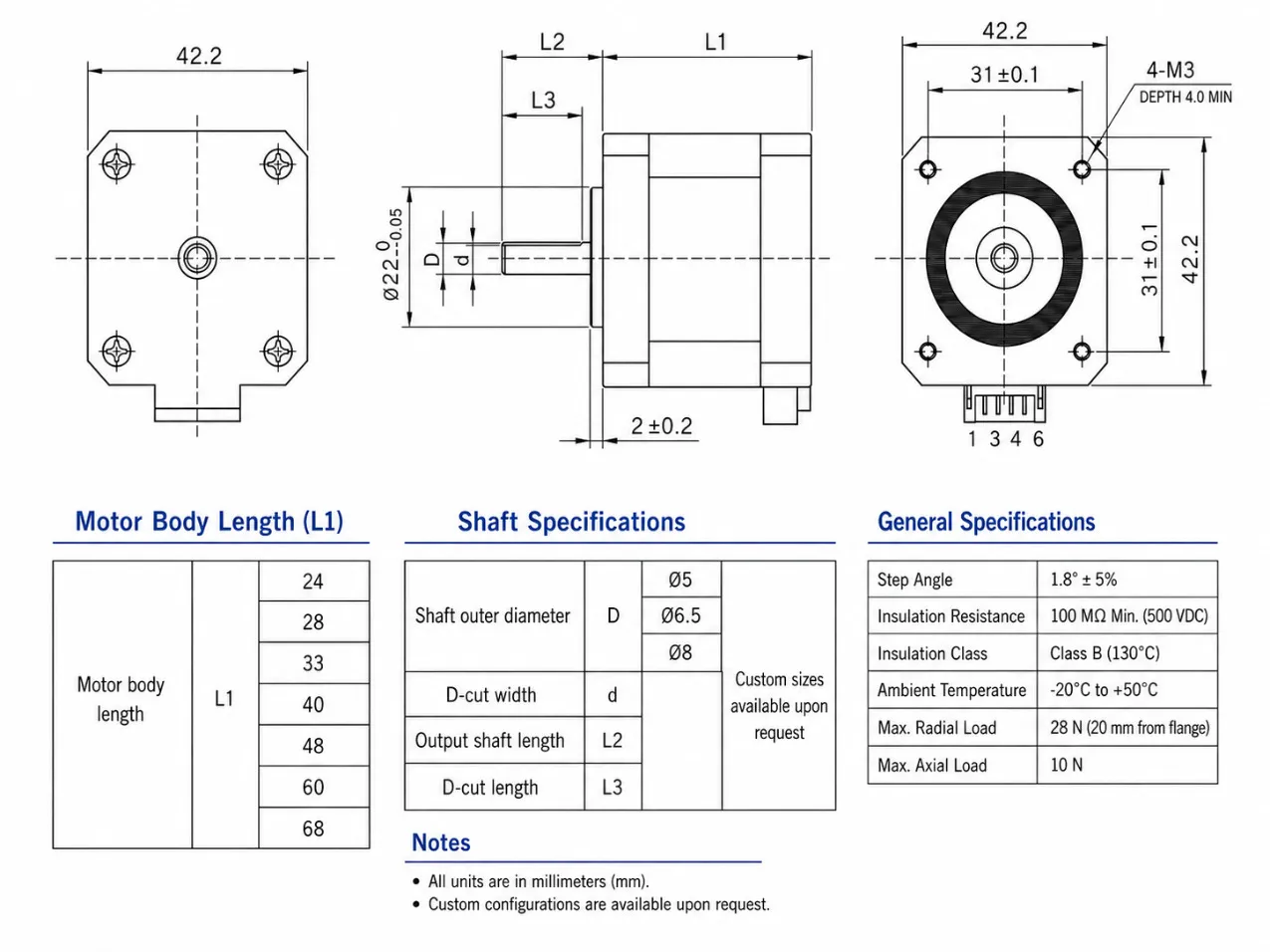
NEMA 17 standardization simplifies the mounting interface, but it does not standardize every dimension. Motor body length, shaft diameter, shaft length, flat geometry, pilot diameter, connector location, lead-wire direction, and rear-shaft configuration can vary between models.
Tolerance stack-up should also be checked. Shaft-to-hub fit, mounting-pilot fit, bracket flatness, bearing alignment, coupling alignment, and pulley position can influence friction and vibration. Misalignment can increase radial load and reduce the usable system torque margin even when the motor itself provides adequate NEMA 17 torque.
Application Examples for NEMA 17 Motor Torque Selection
Light Positioning Mechanism
A sensor-adjustment stage may have low external load and moderate movement speed. In this case, a shorter motor body may provide adequate NEMA 17 torque while reducing installation depth and, depending on the motor design, rotor inertia. Selection should still include positioning repeatability, guide friction, acceleration, holding requirement, and driver compatibility.
Lead Screw Linear Axis
A lead screw converts motor torque into axial motion. Screw lead, efficiency, required thrust, preload, moving mass, guide friction, orientation, and required linear speed all affect motor selection. Increasing screw lead increases travel per revolution but normally raises the motor torque required for the same thrust.
Increasing linear speed also increases the required motor RPM for a given screw lead. The application must therefore be checked against the available nema 17 running torque at that motor speed rather than against holding torque alone.
Belt-Driven Axis
A belt-driven stage requires consideration of pulley radius, required belt force, carriage mass, bearing friction, acceleration, and additional losses associated with belt pretension. A larger pulley increases linear travel per revolution but also increases shaft torque demand for a given tangential force.
During rapid acceleration, inertia may become a major part of the required torque. A motor can move the carriage at constant speed yet lose synchronization during acceleration. For this type of mechanism, available NEMA 17 torque at the actual motor speed is more informative than the zero-speed specification.
Gearbox-Driven Application
A gearbox reduces output speed and increases theoretical torque multiplication. Actual output torque must account for gearbox efficiency and remain within the gearbox’s permitted torque, bearing-load, and thermal limits.
Gearbox backlash, torsional compliance, and efficiency should be evaluated separately because they depend on gearbox architecture, gear mesh, bearing arrangement, materials, and number of stages. A higher reduction ratio by itself does not define mechanical compliance.
For selection, compare required output torque with the motor’s usable torque at the gearbox input speed, then account for ratio and transmission efficiency. Multiplying the motor’s holding-torque value directly by the gear ratio can overstate usable output capability.
Common NEMA 17 Torque Selection Mistakes
One common mistake is selecting the motor with the largest nema 17 holding torque value without checking operating speed. Another is treating all 42 mm-class motors as interchangeable even though body length, shaft geometry, current, inductance, connector position, and thermal characteristics can differ.
Torque units also cause avoidable comparison errors. N·m, N·cm, and kgf·cm should be converted before values are compared. A numerically larger value expressed in N·cm does not necessarily represent more torque than a smaller-looking value expressed in N·m.
Mechanical transmission elements introduce frictional and other losses, so not all motor shaft torque becomes useful load torque. Lead screws, gears, belts, bearings, seals, and preload should be considered where relevant. Acceleration and inertia must also be included for machinery with frequent starts, stops, or reversals.
Finally, nema 17 max torque should not be treated as a universal operating value unless the specification clearly states the test condition. A static maximum, a pull-out value at a given speed, and a permitted continuous operating point describe different conditions.
Information Required for NEMA 17 Torque Selection
A useful motor evaluation requires more than one torque figure. Engineers and procurement teams should provide the mechanical and electrical conditions that define the actual operating point.
- Required operating torque
- Required holding torque
- Normal and maximum motor speed
- Acceleration and deceleration requirements
- Supply voltage
- Available driver current
- Driver type or model
- Duty cycle
- Load type and load variation
- Motor body length limit
- Shaft diameter and shaft length
- Mounting dimensions
- Lead-wire or connector requirements
- Operating temperature
- Lead screw specification, where applicable
- Gearbox ratio, where applicable
- Encoder requirement, where applicable
Providing this information allows NEMA 17 torque to be evaluated against the intended machine rather than against a catalogue value in isolation. For OEM integration, an installation drawing is also useful for checking shaft geometry, mounting tolerances, body length, wiring direction, and available installation space.
Conclusion
NEMA 17 torque should be selected from the actual load, operating speed, electrical conditions, and mechanical interface rather than from holding torque alone.
FAQ
Is NEMA 17 Holding Torque the Same as Running Torque?
No. Nema 17 holding torque is measured at standstill under specified excitation conditions. Nema 17 running torque is a common search term for torque available during rotation, but technical selection should use speed-dependent dynamic torque data at the required operating point.
Available motor torque generally decreases as speed increases because winding inductance, back EMF, and driver and supply conditions limit phase-current development at higher stepping rates. The mechanical load determines how much of that available torque is required for steady motion and acceleration.
Does a Longer NEMA 17 Motor Always Provide More Usable Torque?
No. A longer motor may provide greater static torque, but usable NEMA 17 torque also depends on winding design, phase current, inductance, driver voltage, shaft speed, temperature, and the required motion profile. Body length is one selection parameter, not a direct prediction of dynamic performance.
Should I Choose the Motor with the Highest Torque Rating?
Not automatically. The prominently listed torque specification on many standalone stepper motor datasheets is holding torque. For a moving system, compare required torque with available torque at the intended speed, then verify phase current, supply conditions, inductance, acceleration, transmission losses, motor dimensions, and temperature limits. The correct motor is the one that maintains sufficient operating margin under the actual machine conditions.